Brake-line fastener

A technology of fasteners and brake pipes, applied in the direction of brake components, threaded fasteners, brakes, etc., can solve problems, brake parts waste, waste and other problems

Inactive Publication Date: 2011-03-30
GM GLOBAL TECH OPERATIONS LLC
View PDF4 Cites 2 Cited by
  • Summary
  • Abstract
  • Description
  • Claims
  • Application Information

AI Technical Summary

Problems solved by technology

However, such self-aligning fasteners can still be problematic
[0005] Additionally, the various brake components may inadvertently deform during shipping causing further misalignment between the mechanical fasteners and the brake components
As a result, the initial engagement between fastening components may not be optimal, leading to wasted and scrapped braking components due to cross-thread connections

Method used


Image

  • Brake-line fastener
  • Brake-line fastener
  • Brake-line fastener

Examples


Embodiment Construction

[0014] As required, detailed embodiments of the present invention are disclosed herein; however, it is to be understood that the disclosed embodiments are merely exemplary of the invention, which can be embodied in various forms. Therefore, specific structural and functional details disclosed herein are not to be interpreted as limiting, but merely as a basis for the claims and as a basis for teaching one skilled in the art to employ the present invention in virtually any appropriately detailed structure. representative basis.

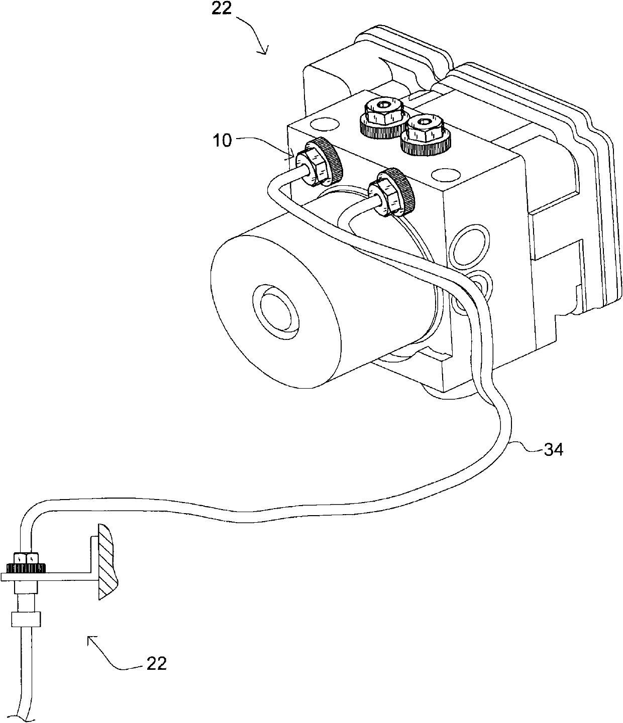
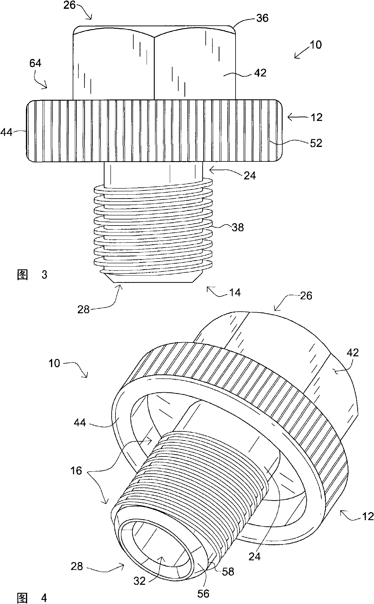
[0015] In general terms, the present invention provides an improved brake line fastener, generally indicated herein by reference numeral 10, adapted for quick manual engagement for securing vehicle brakes. moving parts ( Figure 1-6 ). Typically, the improved brake line fastener 10 includes a manual activation feature 12 ( image 3 ) to help the operator (not shown) overcome limited misalignment. The manual activation feature 12 includes an orienta...


PUM


Abstract

The present invention provides a brake-line fastener adapted for secure engagement of a vehicle braking component with a tubular member, the brake-line fastener including an operator interface and a directional surface associated with one end of the brake-line fastener for rapid manual engagement between the brake-line fastener and the braking component utilizing a complementary threaded receiver.

Description

technical field [0001] This invention relates to mechanical fasteners for vehicle braking systems. More particularly, the present invention relates to an improved tubular fastener and method of connecting a brake line to a brake module associated with a vehicle braking system. Background technique [0002] Vehicle brake line fasteners are well known and subject to various industry specifications. Many of these known fasteners include bores adapted to receive various brake components, including enlarged end brake lines. Generally, to receive these brake components, brake line fasteners are provided to press the enlarged ends of these brake components against the elongated tapered ends of adjacent mating components, thereby securing the respective components in an environmentally-tight manner. [0003] However, many of these brake line fasteners suffer from disadvantages that are addressed by the present invention. For example, some brake line fasteners are connected across...

Claims


Application Information

Patent Timeline
Patent Type & Authority Applications(China)
IPC IPC(8): F16L19/025F16B35/00
CPCB60T17/046F16L19/0283B60T8/3685
Inventor S·卡尔内克
Owner GM GLOBAL TECH OPERATIONS LLC
Why Eureka
Try Eureka