
Arc plasma gun

A technology of arc plasma and spray gun, applied in the direction of plasma, electrical components, etc., can solve the problems of high emission of greenhouse gases, large consumption of coal resources, and low quality of synthesis gas

Inactive Publication Date: 2013-06-12
周开根
View PDF10 Cites 0 Cited by
  • Summary
  • Abstract
  • Description
  • Claims
  • Application Information

AI Technical Summary

Problems solved by technology

[0007] The purpose of the present invention is to overcome the shortcomings of existing plasma spray guns, such as low efficiency and easy ablation of electrodes, to design and manufacture an arc plasma spray gun with high efficiency and difficult electrode ablation, which is used for coal gasification equipment, Garbage biomass gasification device or pyrolysis water hydrogen production device overcomes the low gasification rate, large consumption of coal resources, high emission of greenhouse gases and low quality of synthetic gas produced by directly using water vapor as gasification agent disadvantages to reduce coal resource consumption and reduce greenhouse gas emissions

Method used


Image

  • Arc plasma gun
  • Arc plasma gun
  • Arc plasma gun

Examples


Embodiment 1

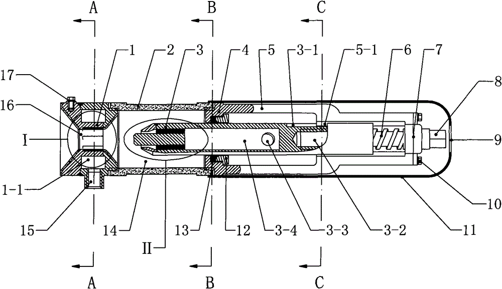
[0036] Example 1 figure 1 In the shown embodiment, arc plasma torch is mainly made up of anode (1), cathode (3), gun barrel (2), backseat (4), air chamber (14) and protective cover (11), wherein: The anode (1) is a hollow annular body structure, the ring center space of the annular body constitutes the spout (16), the annular cooling groove (1-1) is arranged in the annular body, and the annular cooling groove (1-1) has a cooling water interface (15) connected to the There are cooling water vaporization holes (1-2) and steam injection grooves (1-3) on the ring wall between the annular cooling groove (1-1) of the anode (1) and the spout (16), wherein the cooling The water vaporization hole (1-2) is a circular hole structure, and 6 groups of cooling water vaporization holes are arranged in a ring shape, and each group has five cooling water gasification holes; the inlet of the cooling water gasification hole (1-2) is in the ring Cooling tank (1-1), the outlet is connected to the...

Embodiment 2

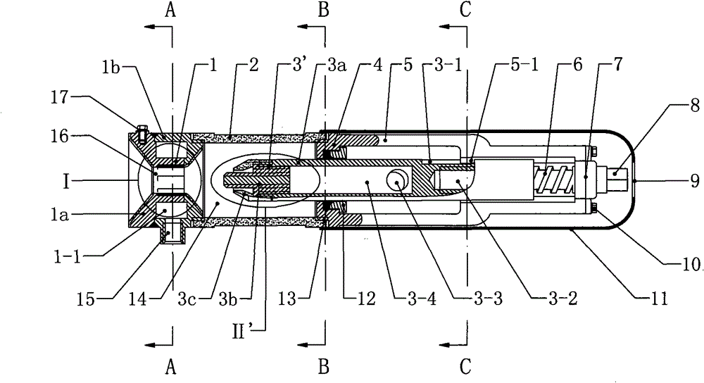
[0037] Example 2 figure 2 In the shown embodiment, replace the cathode (3) in the first embodiment with combined cathode (3 '), the combined cathode (3 ') consists of cathode rod (3a), cathode head (3b) and cathode cap (3c), wherein, the cathode rod (3a) has a tubular structure from the middle section to the front end, and the space in the tube forms a cooling chamber (3-4), and the cooling chamber (3-4) has a working water interface (3-3) connected to it ; The front end of the cathode head (3b) is a tapered conical surface, and the back of the conical surface is a cylindrical entity, and there are vaporization ribs (3b-1) on the rear entity of the cathode head (3b), and the vaporization ribs (3b-1) It is arranged in a multi-piece ring, and the gap between the vaporization ribs (3b-1) forms a vaporization chamber (3-9), and the vaporization fins (3b-1) have an assembly flange (3b-2); the cathode cap ( 3c) Fasten the assembly flange (3b-2) on the cylinder wall at the front en...

Embodiment 3

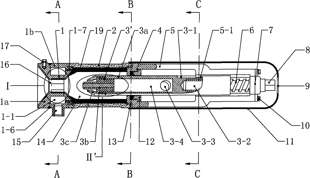
[0038] Example 3 Figure 14In the shown embodiment, arc plasma torch is mainly made up of anode (1), cathode head (3b), cathode cap (3c), gun barrel (2) and cathode base (18), and the gun barrel (2) The rear end is connected to the cathode base (18) to form the gun body, the anode (1), gun barrel (2) and cathode base (18) are coaxially arranged, and the anode (1) is connected to the front end of the gun barrel (2) , the annular center space of the anode (1) constitutes the spout (16), the inner space of the gun barrel (2) forms the air chamber (14), the cathode base (18) constitutes the rear closed end of the gun barrel (2), and the cathode head ( 3b) Set in the gun body, the cathode cap (3c) fastens the cathode head (3b) on the cathode base (18), and the space between the cathode head (3b) and the anode (1) constitutes a discharge space; wherein, the anode (1) It is a hollow annular body structure, and there is a power terminal (17) on the outside of the annular body, and th...


PUM


Abstract

The invention discloses an arc plasma gun and relates to plasma heating equipment. The gun is characterized by consisting of an anode, a cathode, a gun barrel and a back seat, wherein the anode has a hollow annular body structure; a cooling groove is formed in an annular body and provided with a cooling water interface; the cathode has a hollow stick body structure; a cooling cavity is formed in a stick body and provided with a working water interface; the back seat has a disc body structure; the center of a disc body is provided with a passage hole; the anode, the gun barrel and the back seat are arranged coaxially; the back end of the gun barrel is connected to the back seat so as to form a gun body; the anode is connected to the front end of the gun barrel; the annular space of the anode forms a jet orifice; the internal space of the gun barrel forms an air chamber; the front end of the cathode extends into the gun barrel through the passage hole on the back seat; a discharge spaceis formed in the space between the front end of the cathode and the anode; a back stick body of the cathode is outside the gun body; and the working water interface is connected to the cooling cavityof the cathode from the outside of the gun body. The efficiency of the gun is almost 100 percent and the anode and the cathode are protected from being ablated more effectively.

Description

technical field [0001] The invention relates to electric heating equipment, in particular to a plasma heating equipment. Background technique [0002] At present, plasma technology has been widely used, industrially used in plasma ignition, plasma spraying, metal smelting, plasma heating to manufacture nanomaterials, cutting, garbage incineration and waste treatment, etc. In recent years, the technology of using plasma to treat dangerous and harmful wastes and household garbage has developed rapidly. The plasma treatment method is quite different from the general incineration method. This state, accompanied by the discharge phenomenon, will generate active chemicals of excited atoms, excited molecules, dissociated atoms, free atomic groups, atomic or molecular ion groups, and their collisions with other chemical substances. In the plasma generator, the discharge effect causes the working gas molecules to lose the outer electrons and form an ion state, which generates high t...

Claims


Application Information

Patent Timeline
Patent Type & Authority Patents(China)
IPC IPC(8): H05H1/28H05H1/34
Inventor 周开根
Owner 周开根
Learn More