High-power discharge switch gear based on electricity triggered thyristors

A discharge switch and thyristor technology, which is applied in the field of high-power discharge switch devices, can solve problems affecting high pulse power transmission efficiency, pulse rise time and work stability, poor reliability and safety, and slow control response speed, etc., to achieve simplicity Disc spring press-fit self-locking mechanism ensures reliability and reduces complexity

Active Publication Date: 2012-11-14
ZHUZHOU NAT ENG RES CENT OF CONVERTERS
View PDF0 Cites 0 Cited by
  • Summary
  • Abstract
  • Description
  • Claims
  • Application Information

AI Technical Summary

Problems solved by technology

[0003] Traditional discharge switching devices such as gas switches, vacuum trigger switches, solid state switches, laser trigger switches, and magnetic switches have a slow control response speed, are easy to burn out under high current, and have poor reliability and safety, which seriously affects the transmission efficiency of high-pulse power supplies. , pulse rise time and working stability, so it is rarely used as a high-power discharge switch

Method used


Image

  • High-power discharge switch gear based on electricity triggered thyristors
  • High-power discharge switch gear based on electricity triggered thyristors
  • High-power discharge switch gear based on electricity triggered thyristors

Examples


Embodiment Construction

[0028] The following will clearly and completely describe the technical solutions in the embodiments of the present invention with reference to the accompanying drawings in the embodiments of the present invention. Obviously, the described embodiments are only part of the embodiments of the present invention, not all of them. Based on the embodiments of the present invention, all other embodiments obtained by persons of ordinary skill in the art without creative efforts fall within the protection scope of the present invention.

[0029] As a specific embodiment of the present invention based on a high-power discharge switch device based on an electric trigger thyristor, the following will be combined with the attached Figures 1 to 6 The present invention is described further:

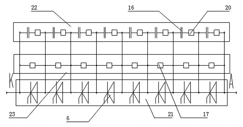
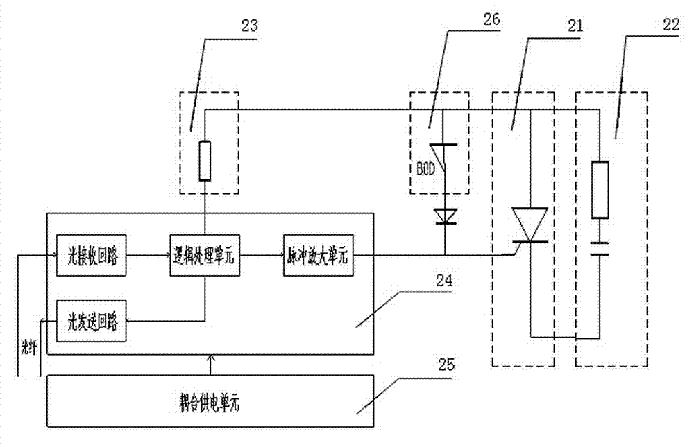
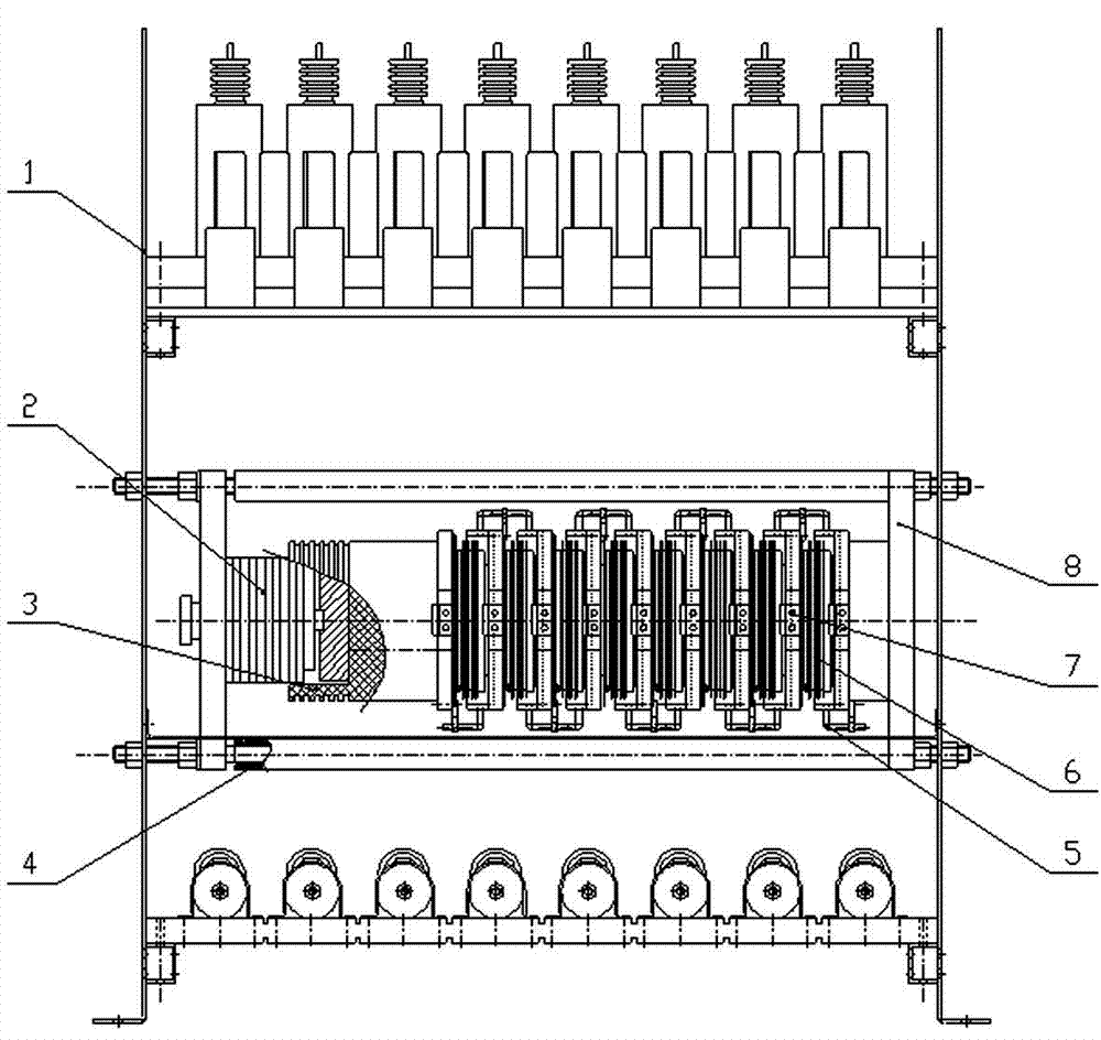
[0030] like Figure 3 to Figure 6 As shown in the schematic diagram of the structure, the high-power discharge switching device based on the electric trigger thyristor adopts a serial modular thyristo...


PUM


Abstract

The invention discloses a high-power discharge switch gear based on electricity triggered thyristors, which has the advantages of simple structure, high reliability and good electric performance and is free of maintenance. The high-power discharge switch gear comprises a modular thyristor series unit, RC absorption circuit units, a static voltage-sharing unit, a trigger unit and a coupling power unit, wherein the modular thyristor series unit comprises more than one thyristors connected in series, the gate poles of thyristors are connected with the trigger unit, the static voltage-sharing unit comprises static voltage-sharing resistors connected to both poles of a single thyristor in series, the RC absorption circuit units are connected to both poles of a single thyristor in series and comprise damping capacitors and dynamic voltage-sharing resistors, the damping capacitors and the dynamic voltage-sharing resistors are connected in series to form a dynamic RC absorption circuit, the trigger unit receives triggering signals from a control system to control the conduction of thyristors and judge whether the thyristors are in normal state, and feeds back state signals to the control system, and the coupling power unit supplies power to the trigger unit.

Description

technical field [0001] The invention relates to a high-power discharge switch device based on an electric trigger thyristor, which is mainly used in application fields involving high-power pulse technology such as impact high-current technology. Background technique [0002] In pulse power technology such as inrush high current technology, the discharge switch is an essential device. Its function is to release the energy charged by the high-power pulse power supply to the transmission line to the load with a very high power density in a very short time (the shortest can be nanoseconds). [0003] Traditional discharge switching devices such as gas switches, vacuum trigger switches, solid state switches, laser trigger switches, and magnetic switches have a slow control response speed, are easy to burn out under high current, and have poor reliability and safety, which seriously affects the transmission efficiency of high-pulse power supplies. , pulse rise time and working sta...

Claims


Application Information

Patent Timeline
Patent Type & Authority Patents(China)
IPC IPC(8): H02M1/092H02M1/32
Inventor 黄燕艳王卫安邓建华谭胜武周方圆王才孝杨磊马雅青段世彦沈辉易海泉张定华周靖刘彤
Owner ZHUZHOU NAT ENG RES CENT OF CONVERTERS
Why Eureka
Try Eureka