
Formulation of a metalworking fluid

A metal processing and fluid technology, applied in the petroleum industry, base materials, lubricating compositions, etc., can solve the problems of expensive, difficult maintenance, lack of protective barrier film, etc.

Inactive Publication Date: 2011-02-09
凯密特尔有限公司
View PDF5 Cites 19 Cited by
  • Summary
  • Abstract
  • Description
  • Claims
  • Application Information

AI Technical Summary

Problems solved by technology

However, most consumers continue to use oil-based products because of their good lubricity at relatively low cost and because of increased maintenance corrosion issues associated with synthetic process fluids
Synthetic machining fluid sumps, lacking the protective barrier film provided by oil, can corrode and "freeze" machined system bolts, making maintenance difficult
Also, high-lubricity synthetic products are more expensive than oil-based products of similar lubricity
The reduced physical lubricity of semi-synthetic process fluids on a cost basis limits their use in heavy-duty operations

Method used


Image

  • Formulation of a metalworking fluid
  • Formulation of a metalworking fluid
  • Formulation of a metalworking fluid

Examples


Embodiment 1

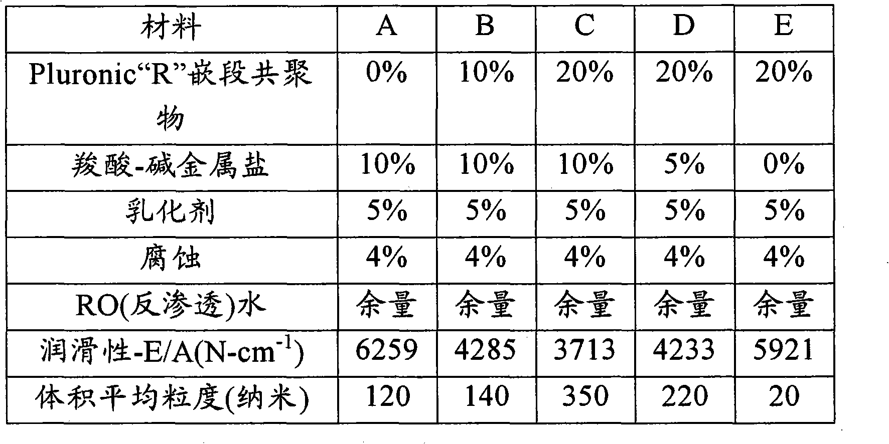
[0077] Table 1

[0078]

[0079] Materials A-E of Table 1 were used in a tapping torque operation involving the tapping of 6061 aluminum. The concentrate was first diluted to a 7.5% by volume solution prior to testing. The tapping torque test is a quantitative measure of the lubricity of a metalworking fluid. Its ASTM standard method name is D5619. Tapping torque reflects the industrial machining process better than other tests, which are usually performed by rubbing two metal surfaces together. It is an excellent method for identifying the machinability of metalworking fluid (MWF) products in the laboratory. Tapping torque results have been shown to be closely related to field machinability.

[0080] The Tapping Torque Tester is designed to measure the lubricity of MWF while actually cutting. During the tapping operation, the tapping torque meter measured 250 momentary torques as the tap advanced through the depth of cut. Specialized software then facilitates the ana...

Embodiment 2

[0086] The materials of Table 1 were used in particle size operations involving the measurement of volume average particle size in nanometers. The concentrate was first diluted to a 7.5% by volume solution with water prior to testing. Particle-sizing instruments use high-efficiency dynamic light scattering to quantify particle sizes from 20-100,000 nanometers.

[0087] All samples were diluted to 7.5% by volume prior to testing. The resulting particle sizes are shown in Table 1.

Embodiment 3

[0089] Material C of Table 1 was tested for particle size at two different concentrations and evaluated for appearance and emulsion stability at each concentration. The results are presented in Table 2, which showed large average particle size, opaque appearance and excellent stability at each concentration. Larger particle sizes are characteristic of better lubricants. Typical synthetic MWFs form clear solutions on dilution with particle sizes less than 100 nm. Diluted sample C had a particle size 3.5-20 times larger than the largest size observed for typical synthetic MWFs.

[0090] Table 2

[0091]

[0092]

[0093] From Examples 1-3 it can be seen that the best lubricity and particle size was obtained with Sample C, which incorporated 10% carboxylic acid-alkali salt and 20% Pluronic "R" block Copolymers combined. This ratio results in maximum volume average particle size and maximum lubricity.

[0094] It is also evident from this example that the lubricity of t...


PUM


Abstract

Non-oil containing metalworking fluids, also known as synthetic metalworking fluids having an engineered particle size of greater than 120 nanometers upon dilution. The expansive particle size results in a substantial increase in lubricity, suitable for the heavy-duty operations previously attainable only with oil-containing products. Additionally, this non-oil containing metalworking lubricant optionally incorporates positive attributes of oil-containing products, including excellent corrosion inhibition and heavy-duty operation capable lubricity.

Description

[0001] related application [0002] [Not applicable] [0003] Federally Sponsored Research or Development [0004] [Not applicable] [0005] [Microfiche / Copyright License Scope] [0006] [Not applicable] Background of the invention [0007] The present invention relates to oil-free metalworking fluids, also known as synthetic metalworking fluids. [0008] Metalworking is defined as shaping a metal workpiece to conform to a desired set of geometric specifications. Metalworking consists of two basic categories: cutting and forming. Cutting operations include grinding, turning, milling, tapping, broaching and hobbing. Forming operations include hot and cold rolling, drawing, forging, stamping and die cutting. [0009] Metalworking fluids are necessary in both cutting and forming operations. They must provide lubrication between the workpiece and the tool, as well as cooling by removing heat generated during metalworking operations. [0010] Lubrication is defined as the ...

Claims


Application Information

Patent Timeline
IPC IPC(8): C10M103/00
CPCC10M2215/04C10M2217/026C10M2207/04C10M173/00C10M2207/125C10M2209/109C10M2223/04C10M2215/042C10M2217/024C10N2220/142C10N2250/02C10M2207/16C10M2215/223C10N2230/24C10M2223/043C10M2209/104C10M2209/108C10M2209/103C10M2209/105C10M2207/283C10M2201/083C10M2219/044C10N2210/01C10M2217/028C10N2240/40C10M2227/066C10N2220/082C10M2209/084C10M173/02C10M2207/10C10M2201/062C10M2215/224C10N2230/06C10M2209/04C10M2201/087C10M169/045C10M2209/1075C10M2209/1055C10M2209/1045C10M2207/40C10M2207/126C10M2207/122C10N2020/06C10N2030/16C10N2030/06C10N2030/12C10N2040/20C23F11/10C23F11/126C23F11/143C10N2020/091C10N2010/02C10N2030/24C10N2050/01C10M103/00C10M169/04
Inventor L·E·孔德利J·崔
Owner 凯密特尔有限公司
Learn More