Particle comprising core and shell and applications thereof
A particle and application technology, applied in the direction of transportation and packaging, nanotechnology for materials and surface science, fibrous fillers, etc., can solve the problems of no phase conversion, difficulty, and difficulty, and achieve low operating costs and use Simple, low-cost effect
- Summary
- Abstract
- Description
- Claims
- Application Information
AI Technical Summary
Problems solved by technology
Method used
Image
Examples
Embodiment 1
[0127] Example 1 Oxidation of TiN.
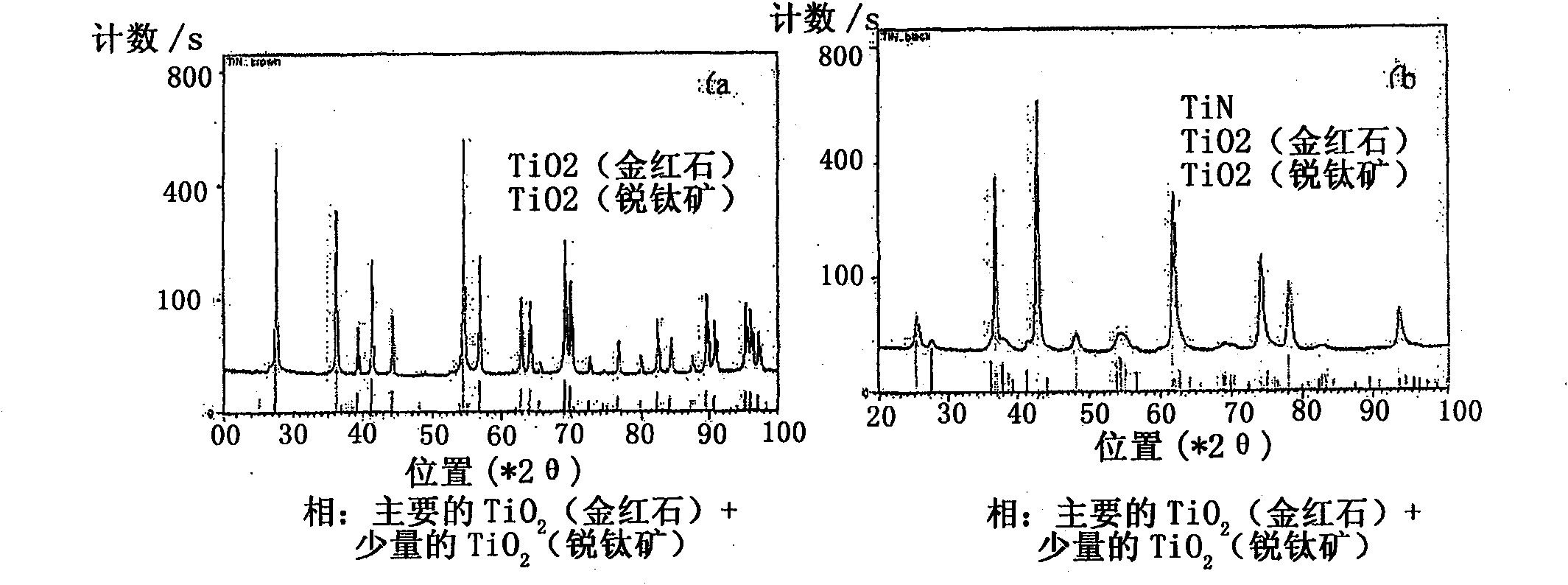
[0128] TiN powder in O 2 Heat treatment at 400-600°C for 1 hour. Both 1.45g and 0.25g TiN powders start to oxidize at 500°C. At 600°C the TiN powder is completely oxidized and the existing anatase phase transforms into a rutile phase. 500°C is the most suitable temperature for obtaining the maximum amount of anatase within the range.
[0129] Figure 1 shows the O in the mixed gas 2 (%) Influence on the crystal structure of the oxidized TiN powder. For 0.25 g of TiN powder, anatase is mainly formed at 4–19% O 2 , for 1.45 g of TiN powder, anatase is mainly formed in 2–6% O 2 . According to Figures 1 and 2, containing about 20% by weight (eg 15-25% by weight) of TiO 2 The samples of have anatase as the main phase on the surface of TiN powder.
[0130] Figure 3 shows the effect of the amount of TiN powder on the formation of TiO 2 Quantitative impact. The TiN powder was heated at 500°C for 1 hour in 2 different atmospheres. 5% O in...
Embodiment 2
[0133] Example 2TiN core-TiO 2 The absorption of light by the shell powder.
[0134] Figure 7 is the TiN core-TiO 2 Optical absorption spectrum of shell powder. Made of 4% TiN and 96% TiO 2 It is true that the composed powder absorbs light above UV light (wavelength (λ)2 The composed powder absorbs light below 850nm. Both powders, especially the one with high TiN content, absorb a wide range of visible light (λ > 387 nm).
Embodiment 3
[0135] Example 3TiN core-TiO 2 Photocatalytic activity of shell powders.
[0136]The photocatalytic activity of these powders was evaluated by photodegrading acid orange 7 (AO7), an organic compound commonly used as an azo dye, under a halogen lamp (4002 Shell powder-water solution mix. It is worth noting that azo dyes are generally difficult to break down due to their deliberate design resistance to degradation. However, Figure 8 shows that both powders can degrade AO7 particularly rapidly after one hour of exposure to the halogen lamp. This phenomenon shows the strong photocatalytic activity of the particles of the present invention.
[0137] Photocatalytic reactions strongly depend on the distance from the light source and the surface area of the powder used. Solutions containing low concentrations of powder showed relatively high rates of photodegradation. This can be attributed to a reduction in powder surface area due to agglomeration, or to light scattering by the...
PUM
| Property | Measurement | Unit |
|---|---|---|
| thickness | aaaaa | aaaaa |
| thickness | aaaaa | aaaaa |
| size | aaaaa | aaaaa |
Abstract
Description
Claims
Application Information
 - R&D Engineer
- R&D Manager
- IP Professional
- Industry Leading Data Capabilities
- Powerful AI technology
- Patent DNA Extraction
Browse by: Latest US Patents, China's latest patents, Technical Efficacy Thesaurus, Application Domain, Technology Topic, Popular Technical Reports.
© 2024 PatSnap. All rights reserved.Legal|Privacy policy|Modern Slavery Act Transparency Statement|Sitemap|About US| Contact US: help@patsnap.com


