Fuel tank for motor vehicles made of thermoplastic plastic

A technology for fuel tanks and fuel tanks, which is applied to vehicle components, the arrangement combined with the fuel supply of internal combustion engines, and the lower structure, which can solve the problems of reducing the compressive strength of plastic tanks and achieve the effect of reducing the pressure per unit area

Active Publication Date: 2014-11-05
KAUTEX TEXTRON
View PDF11 Cites 0 Cited by
  • Summary
  • Abstract
  • Description
  • Claims
  • Application Information

AI Technical Summary

Problems solved by technology

This transfer of force can lead to creep of the plastic in the area of ​​the connection, thus reducing the compressive strength of the plastic box

Method used


Image

  • Fuel tank for motor vehicles made of thermoplastic plastic
  • Fuel tank for motor vehicles made of thermoplastic plastic
  • Fuel tank for motor vehicles made of thermoplastic plastic

Examples


Embodiment Construction

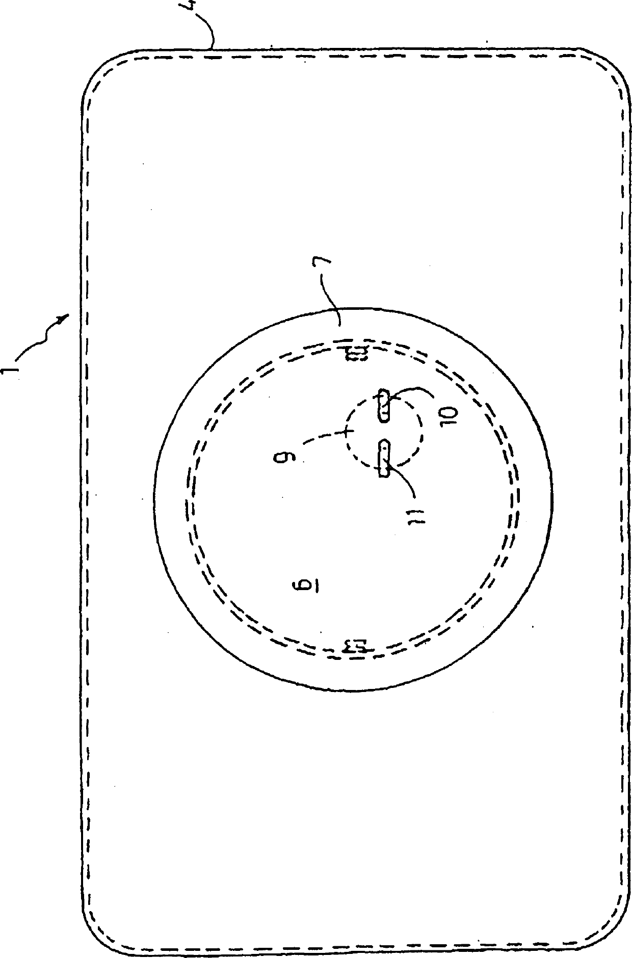
[0030] exist figure 1 shows a fuel tank 1 according to the invention. The fuel tank 1 is formed in a known manner as a fuel tank made of thermoplastic. The tank can be produced, for example, in one piece by extrusion blow molding. figure 1 A greatly simplified sectional view of a fuel tank 1 according to the invention is shown. For reasons of simplification, the filling pipes of the fuel tank 1 and the means for filling and venting are not shown.

[0031]The tank wall 4 of the fuel tank 1 is provided with an opening 6 above the installation location and an opening 5 below the installation location. The two openings 5 ​​, 6 are arranged aligned with one another in mutually opposing sections of the tank wall and have substantially the same diameter. Furthermore, the openings 5 ​​, 6 are also provided as circular openings in the tank wall 4 . A delivery unit 2 extending over the entire height of the fuel tank is inserted into the openings 5 ​​, 6 and accommodates a fuel pump...


PUM


Abstract

The invention relates to a thermoplastic fuel tank (1) for motor vehicles, with at least on stiffening element within the fuel tank (1), wherein the stiffening element extends between two opposite tank walls (4) in such a manner that it counteracts deformation caused by internal pressure of the fuel tank (1). According to the invention, two ends of the stiffening element arranged within the fuel tank (1) engage behind the tank wall (4) from the outside.

Description

technical field [0001] The invention relates to a fuel tank for motor vehicles made of thermoplastics, comprising at least one reinforcement in the fuel tank, wherein the reinforcement extends between two opposing tank walls such that the reinforcement resists Deformation caused by the internal pressure of the fuel tank. Background technique [0002] The fuel tanks used in automobiles today consist mainly of thermoplastics and are manufactured according to the extrusion blow molding method. The internals and additional devices required for operation, such as splash-proof internals, breather valves and lines, fuel pumps, sensors, splash guards, etc., can be blow-molded around during the production of the fuel tank or subsequently inserted into the finished tank . It is known from the prior art, for example, to insert a delivery unit comprising a splash tank and a fuel pump as a so-called "drip-in" solution via an opening on the upper side of the fuel tank in the fuel tank....

Claims


Application Information

Patent Timeline
Patent Type & Authority Patents(China)
IPC IPC(8): B60K15/03
CPCB60K2015/03111B60K15/03177
Inventor K·格贝特U·卡尔施
Owner KAUTEX TEXTRON
Why Eureka
Try Eureka