
Shale oil single-stage serial hydrocracking technology method

A technology for hydrocracking and shale oil, applied in hydrotreating process, hydrocarbon oil cracking, petroleum industry and other directions, can solve the problems of affecting the cracking effect, reducing the acid center, unable to fully exert the effect of catalyst, etc.

Active Publication Date: 2011-01-12
CHINA PETROLEUM & CHEM CORP +1
View PDF5 Cites 37 Cited by
  • Summary
  • Abstract
  • Description
  • Claims
  • Application Information

AI Technical Summary

Problems solved by technology

Since the nitrogen content of shale oil is about 1.0% to 2.0%, or even higher, the concentration of ammonia in the refined effluent gas is relatively high, and ammonia is easily adsorbed on the acid sites of the cracking catalyst, which reduces the acid sites and cannot fully utilize the catalyst. The role of the cracking effect

Method used


Image

  • Shale oil single-stage serial hydrocracking technology method

Examples


Embodiment 1

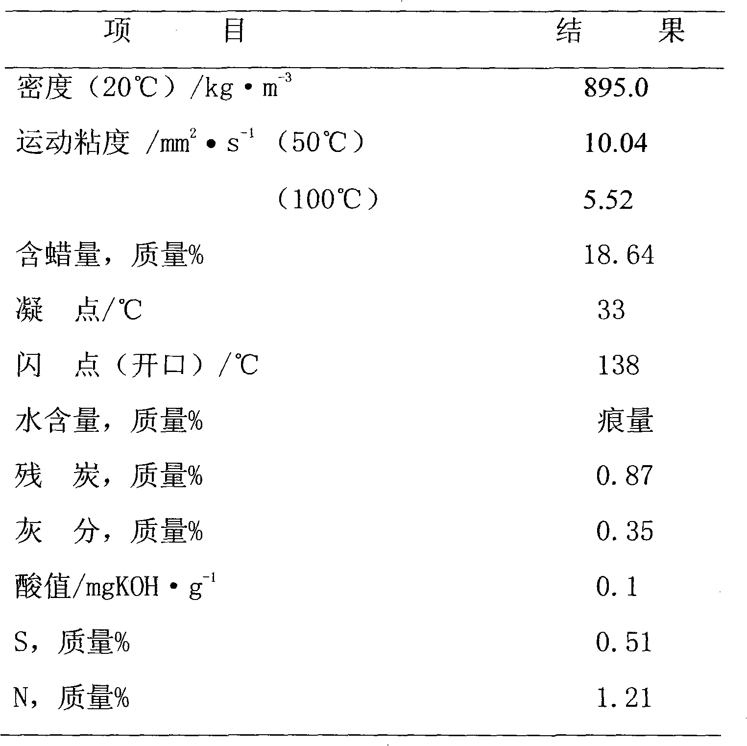
[0019] The hydrofining catalyst is FF-26, the hydrocracking catalyst is FC-14, at a reaction temperature of 360°C, a reaction pressure of 8.0MPa, and a refining volume space velocity of 0.3h -1 , hydrogen oil ratio 1000:1, cracking volume space velocity 0.3h -1 , operating under the condition of hydrogen oil ratio of 400:1. The hydrocracking catalyst adopts two catalyst beds, each catalyst bed accounts for 50% of the total catalyst volume, the upper part uses FC-14B, and the lower part uses FC-14A. The conventional process refers to the hydrocracking operation in which the hydrorefining reaction effluent enters the top of the hydrocracking reactor, and gas-liquid is collected and flows downward. The reaction results are shown in Table 2.

[0020] Table 2 Example 1 data

[0021] project

Embodiment 2

[0023] At a reaction temperature of 420°C, a reaction pressure of 10.0MPa, and a refined volumetric space velocity of 0.5h-1 , hydrogen oil ratio 800:1, cracking volume space velocity 0.8h -1 , operating under the condition of hydrogen oil ratio of 300:1. The hydrocracking catalyst is a mixture of FC-14B and FC-14A at a volume ratio of 1:1. The results are shown in Table 3.

[0024] Table 3 Example 2 data

[0025] project

Embodiment 3

[0027] At a reaction temperature of 390°C, a reaction pressure of 15.0MPa, and a refined volumetric space velocity of 0.8h -1 , hydrogen oil ratio 800:1, cracking volume space velocity 0.5h -1 , operating under the condition of hydrogen oil ratio of 150:1. The hydrocracking catalyst is FC-14A. The results are shown in Table 4.

[0028] Table 4 Example 3 data

[0029] project

[0030] The comparative test data show that the application of the technology of the invention avoids the influence of ammonia on the hydrocracking catalyst, the cracking effect is obvious, and the yield of light oil is high.


PUM


Abstract

The invention discloses a shale oil single-stage serial hydrocracking technology method. A shale oil raw material and hydrogen are in cocurrent flow to feed a hydrofining reactor from the upper part; in the presence of hydrofining catalyst, hydrofining reaction is carried out; hydrofining reaction outflows feed to the upper part of a hydrocracking reactor; the upper part of the hydrocracking reactor is subject to gas-liquid separation; gas phase is discharged from the top of the hydrocracking reactor; liquid phase carries out hydrocracking reaction with reverse flow of the hydrogen which enters the hydrocracking reactor from the bottom of the hydrocracking reactor on hydrocracking catalyst; after hydrocracking reaction ends, the liquid phase product is discharged out of from the bottom ofthe hydrocracking reactor; and the gas phase and the gas phase separated from the hydrofining reaction outflows are jointly discharged from the top of the hydrocracking reactor. The method of the invention solves the deficiencies of low yield and the like of hydrocracking light products because nitrogen content is high in the shale oil in the prior art; meanwhile, the method can improve product quality and has simple processes and stable operation.

Description

technical field [0001] The invention relates to a shale oil hydrogenation process, in particular to a shale oil one-stage series hydrocracking process for improving the yield and quality of light fuel oil. Background technique [0002] Shale oil is a liquid product obtained by thermal decomposition of kerogen in oil shale. In addition to a large amount of unsaturated hydrocarbons, shale oil also contains many non-hydrocarbon compounds such as sulfur, nitrogen and oxygen, and has a high freezing point. Unsaturated hydrocarbons and non-hydrocarbon compounds in shale oil are the main reasons for the increase of oil colloid and the formation of sediment, resulting in poor stability and black color. High freezing point affects its performance. Therefore, when producing light products from shale oil, it is necessary to remove non-hydrocarbon compounds and saturated olefins to lower the freezing point so as to ensure product quality. [0003] Hydrocracking is the process of cataly...

Claims


Application Information

Patent Timeline
IPC IPC(8): C10G65/12C10G47/00
Inventor 苏重时李景斌姚春雷赵桂芳刘灏
Owner CHINA PETROLEUM & CHEM CORP
Learn More