
Method for transporting aluminum milling scraps to complexification workshop through pipelines

A technology for workshops and milling chips, which is applied in the field of conveying aluminum milling chips to compound workshops. It can solve the problems of large forklift or car transportation, limited number of material boxes, and aluminum milling chips that cannot be smelted again, so as to improve production efficiency. The effect of saving repeated transportation and simple structure

Active Publication Date: 2011-01-05
CHINA NON-FERROUS METALS PROCESSING TECH CO LTD
View PDF3 Cites 1 Cited by
  • Summary
  • Abstract
  • Description
  • Claims
  • Application Information

AI Technical Summary

Problems solved by technology

[0003] The disadvantages of transporting aluminum milling chips to the chemical plant by forklift or car are:
[0004] 1. The amount of aluminum milling chips produced by face milling is relatively large, and it occupies more material boxes, resulting in a large amount of transportation by forklifts or cars
[0005] 2. Since the material box is open, in case of bad weather, especially in rainy or snowy weather, the rain or snow will enter the material box during forklift or car transportation, causing the aluminum milling chips to contain moisture, and the aluminum containing moisture will Milling chips cannot be directly remelted, so the aluminum milling chips have to be dried or dried naturally, which reduces production efficiency
[0006] 3. When the bad weather is long, due to the limited number of material boxes, there will be no place to store a large amount of aluminum milling chips, which will bring a lot of trouble to the completion of production tasks

Method used


Image

  • Method for transporting aluminum milling scraps to complexification workshop through pipelines

Examples


Embodiment Construction

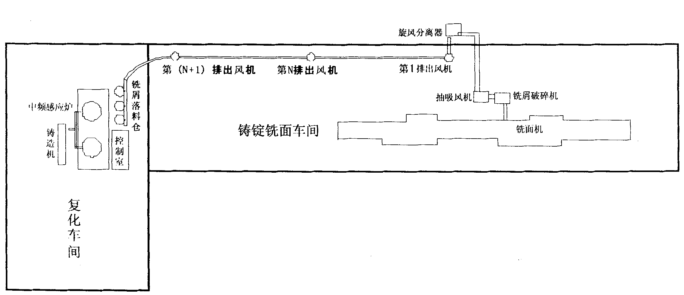
[0017] Combine figure 1 The equipment involved in the present invention includes the milling machine, suction fan, milling chip crusher and cyclone separator in the ingot milling workshop, as well as the milling chip blanking bin in the compounding workshop, and the pipeline is installed in the ingot milling workshop And the roof of the compounding workshop and the two ends of the pipe are respectively introduced into the ingot milling workshop and the compounding workshop.

[0018] On the basis of the above, the pipes introduced into the ingot milling workshop are connected to the milling chip crusher after the suction fan is connected. The cyclone separator is installed on the roof of the ingot milling workshop, and the section connected from the suction fan The pipe is connected with the inlet end of the cyclone separator, and the outlet end of the cyclone separator is connected with the first exhaust fan after connecting a short section of pipe. The first exhaust fan is also ...


PUM


Abstract

The invention relates to a method for transporting aluminum milling scraps to a complexification workshop through pipelines, which comprises a surface milling machine, a suction fan, a milling scrap crusher, a cyclone separator and a milling scrap charging bin, wherein the pipelines are erected on the plant top of an ingoting and surface milling workshop and the complexification workshop and led into the workshop; the pipelines led into the ingoting and surface milling workshop are linked with the milling scrap crusher after being linked with the suction fan; the cyclone separator is erected on the plant top of the ingoting and surface milling workshop; a section of the pipelines linked from the suction fan is linked with the inlet end of the cyclone separator, and the outlet end of the cyclone separator is linked with a first exhaust fan and N exhaust fans; the space between the adjacent exhaust fans is controlled between 100 to 120m; and finally, the (N+1)th exhaust fan is directly communicted with the milling scrap charging bin of the complexification workshop. The invention can ensure that the aluminum milling scraps are sucked into the pipelines by the suction fan after being crushed and then transmitted to the milling scrap charging bin of the complexification workshop through the cyclone separator and the exhaust fans with the functions of pressurization and air exhaust so as to carrying out resmelting.

Description

Technical field [0001] The invention belongs to the technical field of aluminum milling chip transportation, and relates to how the aluminum milling chips generated in the ingot milling workshop of the aluminum processing plant can be transported to the compounding workshop in a timely and rapid manner to realize re-smelting, in particular to a kind of aluminum milling through a pipe The method of conveying shavings to the compound workshop. Background technique [0002] In the ingot milling workshop of the aluminum processing plant, the aluminum ingot is generally milled by a milling machine, and the aluminum milling chips produced by the milling are sucked into the crusher by a suction fan for crushing, and the length of the aluminum milling chips after crushing is generally controlled Between 30-60mm, the crushed aluminum milling chips are dropped into the bin through the cyclone separator, the residual air generated by the cyclone separator is discharged into the air, and the...

Claims


Application Information

Patent Timeline
Patent Type & Authority Applications(China)
IPC IPC(8): B65G53/28B65G53/58B65G53/52
Inventor 陈策
Owner CHINA NON-FERROUS METALS PROCESSING TECH CO LTD
Learn More