
Device and method for breakout prediction during slab continuous casting

A slab continuous casting and breakout technology, which is applied in the configuration of indicating equipment/measuring equipment, casting equipment, manufacturing tools, etc., can solve the problem that cracks and breakouts are difficult to catch, cannot display mold copper plates dynamically in real time, and calculate speed Can not meet the real-time calculation and display requirements of continuous casting production and other issues

Inactive Publication Date: 2011-01-05
SHANGHAI BAOSIGHT SOFTWARE CO LTD
View PDF5 Cites 33 Cited by
  • Summary
  • Abstract
  • Description
  • Claims
  • Application Information

AI Technical Summary

Problems solved by technology

However, due to changes in steel types, fluctuations in the composition of mold slag, and the operation of the slag line, the temperature of the copper plate in the mold often appears upside down, resulting in false alarms or missed alarms, and it is almost difficult for cracks and breakouts to occur. caught
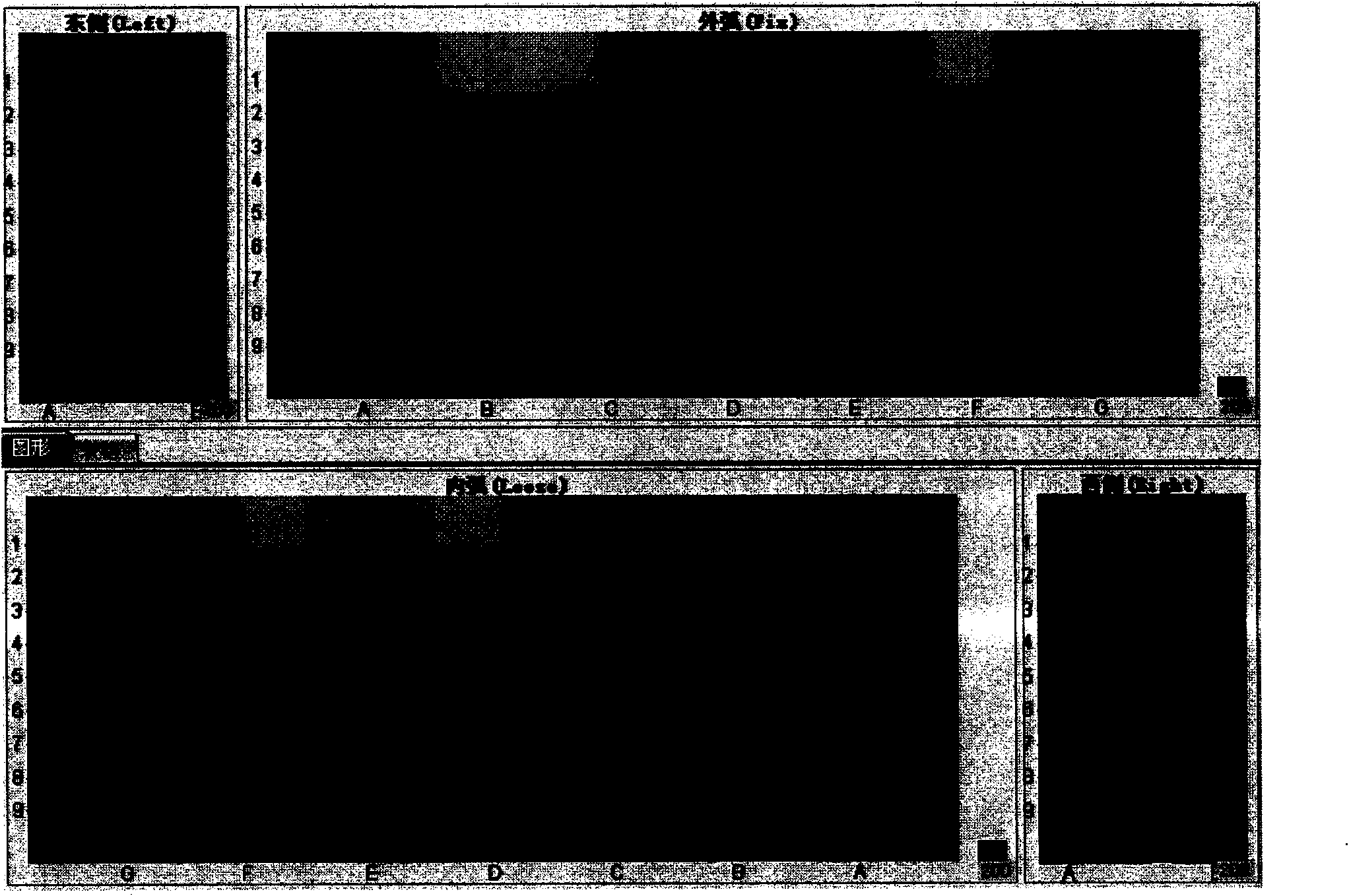
At present, the calculation of the thermal phase diagram of the crystallizer is still in the offline simulation stage. It is obtained through the ideal heat transfer model and continuous optimization based on a large amount of historical data. To accurately display the temperature distribution of the mold copper plate and analyze the solidification of molten steel in the mold, it is impossible to intuitively evaluate the centering of the nozzle, the local cooling effect of the copper plate, the condition of the continuous casting slab shell, and the crystallizer based on the thermal image of the mold copper plate. Taper adjustment, melting and lubrication of mold slag, and crack generation of slab shell in the mold

Method used


Image

  • Device and method for breakout prediction during slab continuous casting
  • Device and method for breakout prediction during slab continuous casting
  • Device and method for breakout prediction during slab continuous casting

Examples


Embodiment Construction

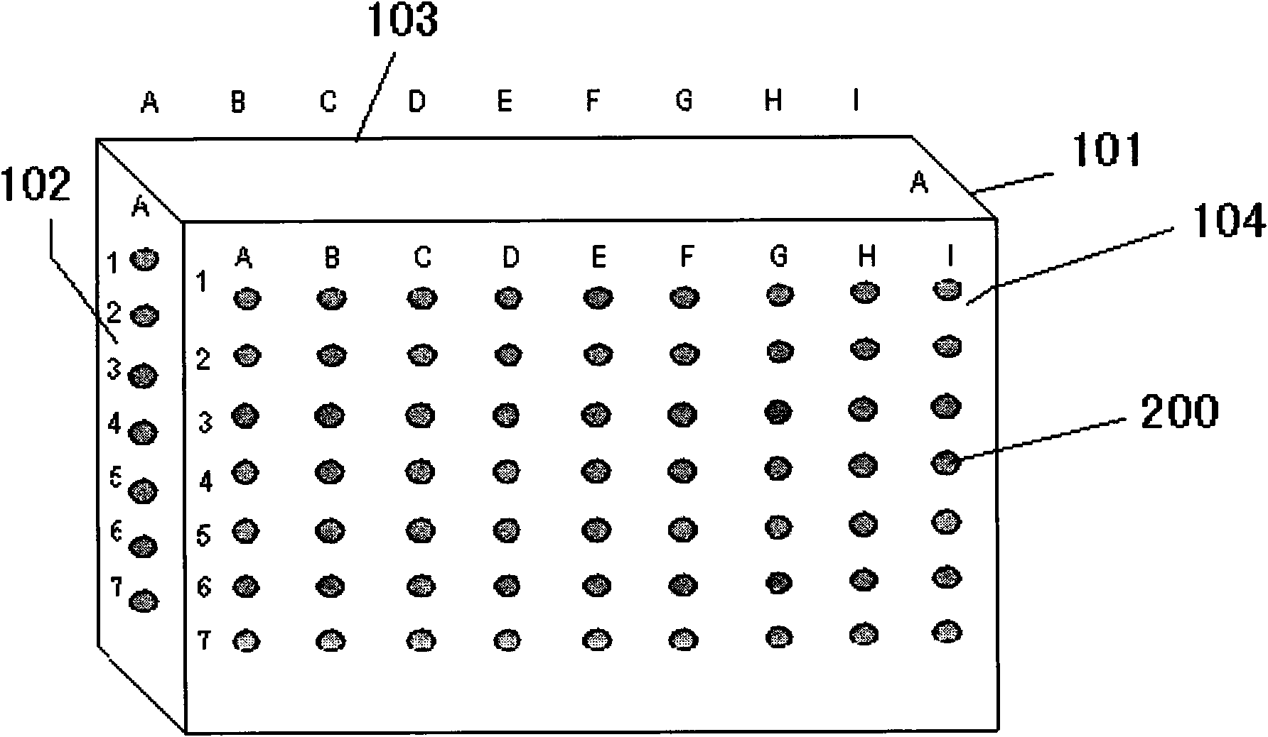
[0015] The invention discloses a device for predicting steel breakout in the slab continuous casting process, such as figure 1 As shown, the side wall of the crystallizer is composed of the west side 101, the east side 102, the outer arc 103 and the inner arc 104 of the surrounding mold, on the side wall of the continuous casting mold from the meniscus of the mold to the outlet of the mold in an array At least 4 rows of thermocouples 200 are arranged in the form of the thermocouples, and the thermocouples are all connected to a calculation control unit, and the calculation control unit calculates the temperature distribution of the molten steel in the crystallizer according to the temperature information of the thermocouples, so as to determine whether leakage is required. Steel alarm.

[0016] At least one row of thermocouples is respectively arranged on the meniscus, from the meniscus to the middle of the mold, and from the middle of the mold to the outlet of the mold, and t...


PUM


Abstract

The invention discloses a device for breakout prediction during slab continuous casting. At least four rows of thermocouples are arranged on a continuous casting mould from a meniscus of the mould to a mould outlet in an array mode, wherein all the thermocouples are connected to a computing control unit; and the computing control unit computes the temperature distribution state of molten steel in the mould according to temperature information of the thermocouples to determine whether a breakout alarm is needed. The invention also discloses a method for realizing the breakout prediction during the slab continuous casting by the device, which comprises the steps that: the computing control unit acquires the temperature information of the thermocouples and establishes a mathematical model for a temperature field of the mould; and when the distance from the position of the maximum temperature of the molten steel in the mould to the height of the mould outlet is less than a preset threshold value, the computing control unit sends out the breakout alarm. Through the device and the method, the alarm can be immediately sent before the occurrence of the breakout and breakout accidents can be avoided.

Description

technical field [0001] The invention relates to a monitoring device in the continuous casting process, in particular to a device for predicting steel breakout in the slab continuous casting process. The invention also relates to a monitoring method in the continuous casting process, especially a method for predicting steel breakout in the slab continuous casting process. Background technique [0002] In the process of producing various steel products in steel plants, there are two methods of using molten steel to solidify and form: the traditional die casting method and the continuous steel casting method. Compared with traditional methods, continuous casting technology has significant advantages such as greatly improving metal yield and billet quality, and saving energy. The specific process of continuous steel casting is: the molten steel continuously passes through the water-cooled crystallizer, condenses into a hard shell, and then is continuously pulled out from the ou...

Claims


Application Information

Patent Timeline
IPC IPC(8): B22D2/00B22D11/18
Inventor 罗庆梅姚若华
Owner SHANGHAI BAOSIGHT SOFTWARE CO LTD
Learn More