
Lens structure of micro-lens driving device and manufacturing method thereof

A lens driving device, lens structure technology, applied in installation, color TV parts, TV system parts and other directions, can solve the problems of threaded structure occupying volume, focus out of focus, excessive power consumption, etc., to solve the problem of contact The effect of friction loss, reduction of defective products, and volume reduction

Active Publication Date: 2010-12-29
TDK TAIWAN
View PDF2 Cites 9 Cited by
  • Summary
  • Abstract
  • Description
  • Claims
  • Application Information

AI Technical Summary

Problems solved by technology

Locking the lens through the thread will make the thread structure occupy a certain volume, and when the lens has an inclination angle relative to the image sensor (Sensor), it will cause the problem of out of focus, but the inclination angle cannot be made due to the limitation of the thread structure Fine-tuning the level, so that the lens is a defective product
[0004] Furthermore, due to the thread structure, the fine-tuning and fixing of the lens and the action of auto-focus will all contact each other and rotate to produce a small amount of friction loss, which will not only consume more power, but also produce a small "beep" sound, which prevents the quality from being improved.

Method used


Image

  • Lens structure of micro-lens driving device and manufacturing method thereof
  • Lens structure of micro-lens driving device and manufacturing method thereof
  • Lens structure of micro-lens driving device and manufacturing method thereof

Examples


Embodiment Construction

[0037] Below in conjunction with accompanying drawing, structural principle and working principle of the present invention are specifically described:

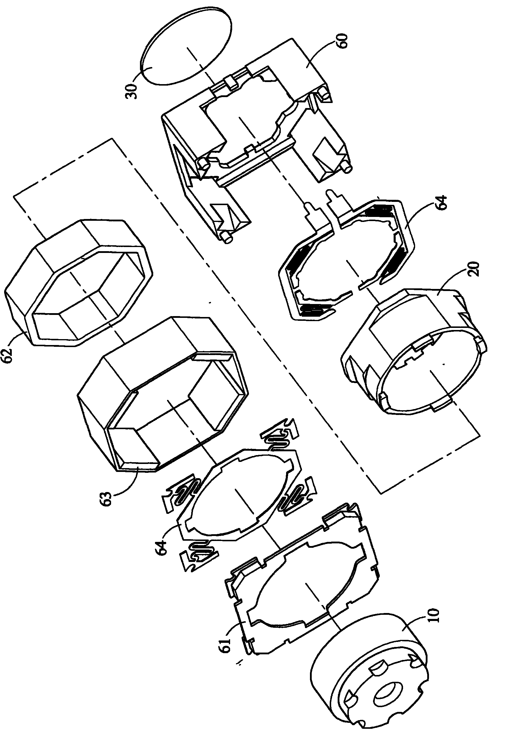
[0038] see figure 1 As shown, it is a three-dimensional schematic diagram of an embodiment of the lens driving device of the present invention. The lens driving device of this embodiment includes a bearing seat 20 for carrying a lens cylinder 10, and the bearing seat 20 is accommodated in a frame 60 of a hollow structure. , the frame 60 can also be covered with an upper cover 61, and the periphery of the bearing seat 20 is covered with a coil assembly 62, and four permanent magnets 63 are arranged outside the coil assembly 62 corresponding to the coil assembly 62. On the bearing seat 20 A set of elastic components 64 are connected to each of the bottom and the bottom, which can suspend and support the bearing seat 20 in the center of the frame 60 , and an image sensor 30 is arranged below the frame 60 .

[0039] The coil asse...


PUM


Abstract

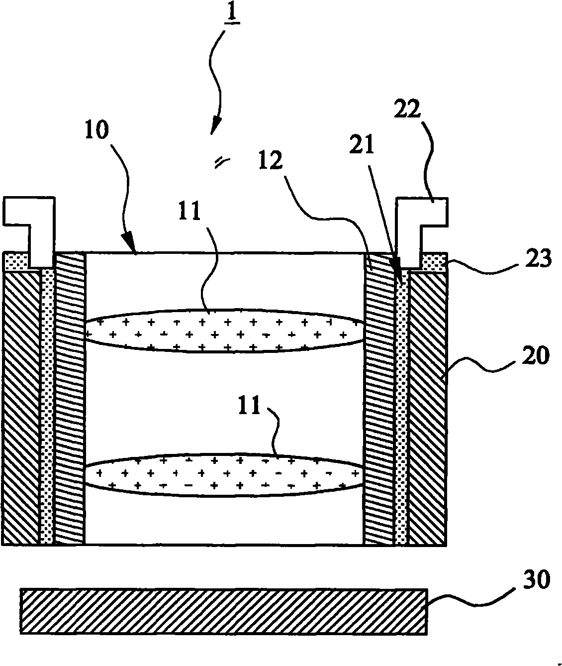
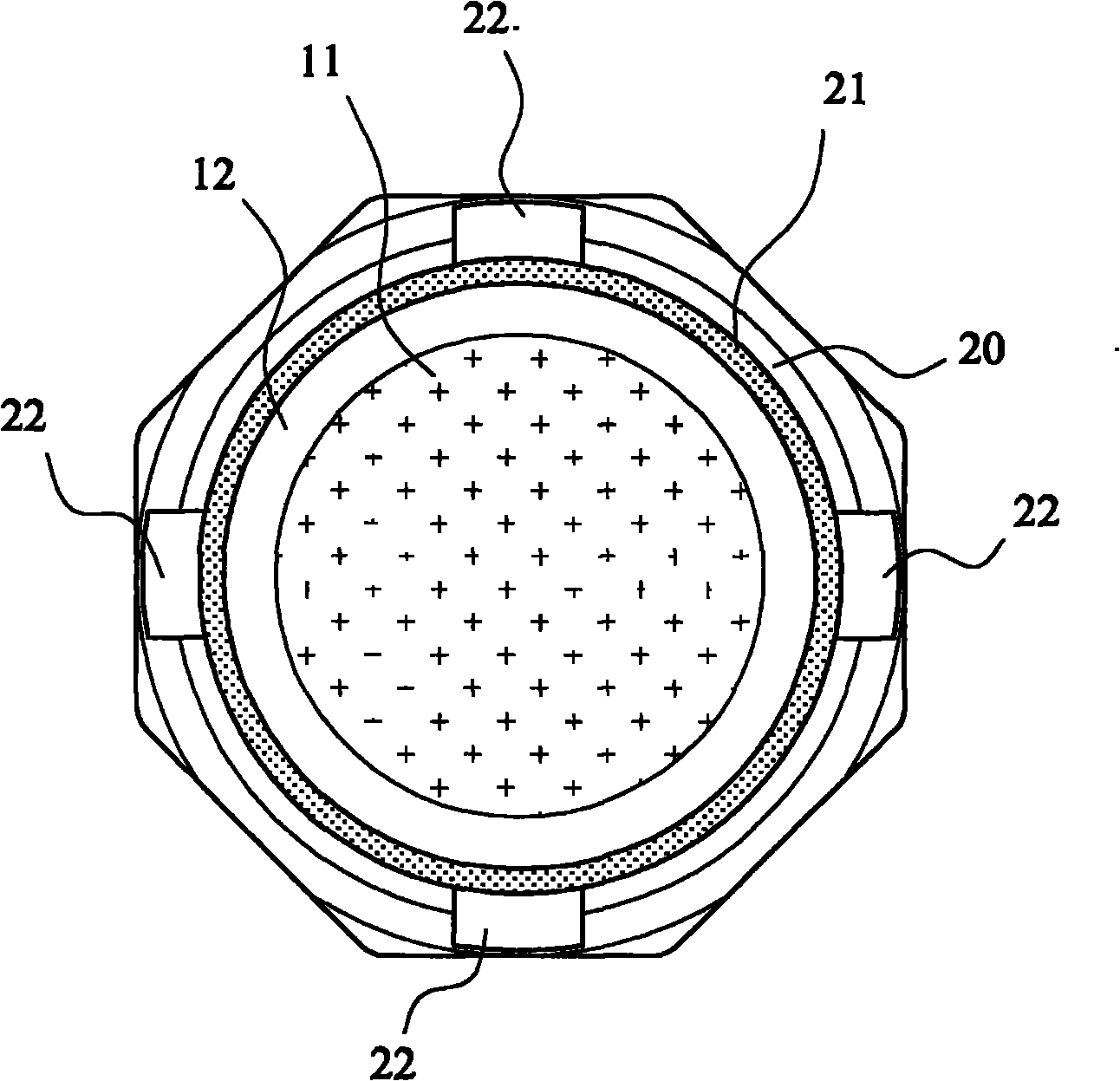
The invention relates to a lens structure of a micro-lens driving device, which comprises a lens cylinder consisting of at least one lens and a lens support part, the lens cylinder and a carrying seat further constitute a lens unit, the lens and the lens support part have no thread structure, and the lens is adhered in the lens support part by a binding agent; and the bearing seat is in the shape of a hollow cylinder, the lens cylinder can be accommodated in the carrying seat, the lens cylinder and the carrying seat also have no thread structure, and the lens cylinder is adhered in the carrying seat by the binding agent, thereby solving the volume occupied by the thread structure, being more miniaturized, and further solving the problem of contact friction loss caused by the thread structure.

Description

technical field [0001] The present invention relates to a lens structure of a miniature lens driving device and its manufacturing method, in particular to a lens unit with a threadless structure and its manufacturing method, which can specifically reduce the structure of the lens, and has the ability to finely adjust the tilt of the lens during the process and focus function. Background technique [0002] Press, the micro lens driving device is mainly to drive the focusing lens to move linearly along the optical axis to focus the image light on the image sensor. It has been widely used in electronic devices with camera or photography functions, such as mobile phones, etc. There are many related driving modes for the lens driving device, such as patent application documents: Japanese Patent Application No. 2008-129597, claiming the priority of Chinese Invention No. 200610157001.2, which discloses a structure that uses a stepping motor to drive the lens to focus , a method in...

Claims


Application Information

Patent Timeline
IPC IPC(8): H04N5/225G02B7/04G03B30/00
Inventor 詹益良
Owner TDK TAIWAN
Learn More