
External optical fiber Bypass equipment and optical signal channel switching method

A technology of optical signals and equipment, applied in optical fiber transmission, electromagnetic wave transmission systems, electrical components, etc., can solve the problems of high replacement cost, difficult upgrade, and low selectability, and achieve high replacement cost, strong selectability, and upgrade convenient effect

Inactive Publication Date: 2010-12-29
深圳市研祥通讯终端技术有限公司
View PDF0 Cites 3 Cited by
  • Summary
  • Abstract
  • Description
  • Claims
  • Application Information

AI Technical Summary

Problems solved by technology

[0004] The technical problem to be solved by the present invention is to provide a switching method for an external optical fiber Bypass device and an optical signal channel in view of the defects of the existing optical fiber network motherboard product with integrated Bypass function, such as low selectability, high replacement cost, and difficult upgrade

Method used

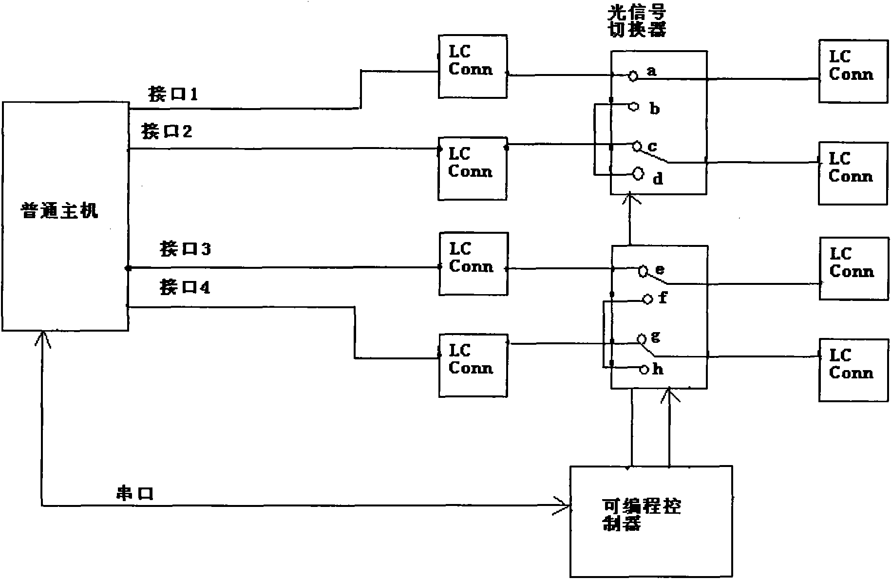
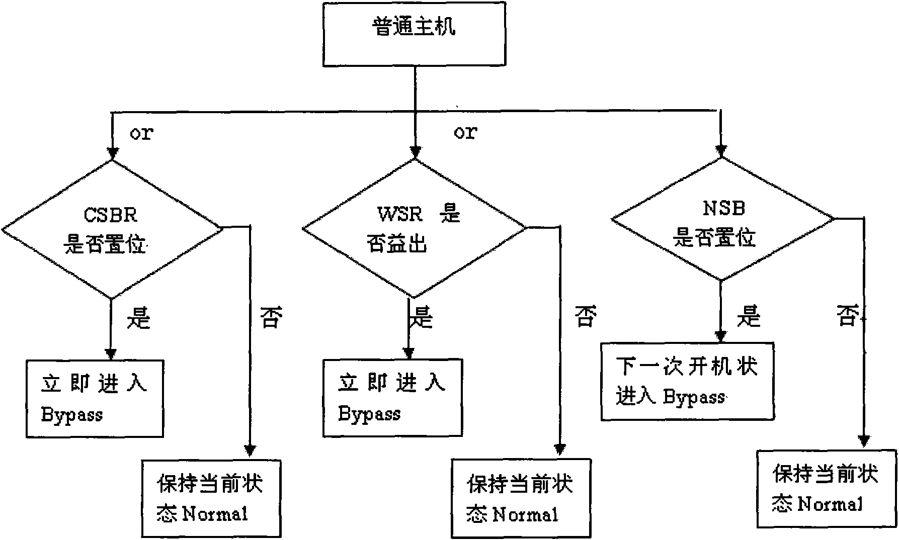

Image

  • External optical fiber Bypass equipment and optical signal channel switching method
  • External optical fiber Bypass equipment and optical signal channel switching method
  • External optical fiber Bypass equipment and optical signal channel switching method

Examples


Embodiment Construction

[0023] In order to make the objectives, technical solutions and advantages of the present invention clearer, the present invention will be further described in detail below with reference to the accompanying drawings and embodiments. It should be understood that the specific embodiments described herein are only used to explain the present invention, but not to limit the present invention.

[0024] An embodiment of the present invention provides an external optical fiber bypass device, such as figure 1 As shown, it includes: an optical signal converter, a programmable controller and a power converter (not shown in the figure), the optical signal converter is connected to the programmable controller, and the programmable controller is connected to the For a common host (that is, a host without an integrated Bypass function), in this embodiment, the interface may be a serial port, a parallel port or a USB interface.

[0025] The power converter provides power for the optical si...


PUM


Abstract

The invention relates to external optical fiber Bypass equipment. The equipment comprises an optical signal converter, a programmable controller and a power converter, wherein the optical signal converter is connected with the programmable controller; the power converter supplies power to the optical signal converter and the programmable controller; the programmable controller is used for receiving a control signal sent by a host and indicating the optical signal converter according to the control signal; and the optical signal converter is used for switching optical signal channels according to the indication of the programmable controller. On the host with an optical fiber network card, a Bypass function can be realized by allocating the external optical fiber Bypass equipment without replacing any original hardware equipment; and therefore, the equipment has the characteristics of high selectivity, low replacement cost and convenient upgrade.

Description

technical field [0001] The present invention relates to the technical field of optical signal processing equipment, and more specifically, relates to an external optical fiber bypass equipment and a switching method of an optical signal channel. Background technique [0002] Bypass [bypass function, which can prevent two networks from passing through the system of network security equipment through a specific trigger state (power failure or crash)] equipment, places with high real-time requirements, such as government, telecommunications, education, medical care, electricity It is a necessary network switching system for units such as hospitals, transportation, and scientific research institutes, which plays a decisive role in the protection of single-point failures in the line. The network bypass device is used to protect and prevent various network serial gateway devices (such as network firewalls, anti-virus gateways, anti-spam gateways, etc.) from becoming a single point...

Claims


Application Information

Patent Timeline
Patent Type & Authority Applications(China)
IPC IPC(8): H04B10/12H04B10/25
Inventor 唐先文
Owner 深圳市研祥通讯终端技术有限公司
Learn More