
Welding setting device, welding robot system and welding setting method

A welding robot and setting device technology, applied in welding equipment, arc welding equipment, metal processing equipment, etc., can solve the problems of shortened welding time and inability to realize welding, and achieve the effect of shortening welding time

Active Publication Date: 2010-11-24
KOBE STEEL LTD
View PDF4 Cites 43 Cited by
  • Summary
  • Abstract
  • Description
  • Claims
  • Application Information

AI Technical Summary

Problems solved by technology

At this time, after using two welding robots, the overall welding cannot be completed in half the time (2 times the speed) of running alone
That is, the effect of shortening the welding time by using two welding robots at the same time cannot be fully exerted

Method used


Image

  • Welding setting device, welding robot system and welding setting method
  • Welding setting device, welding robot system and welding setting method
  • Welding setting device, welding robot system and welding setting method

Examples


no. 1 approach

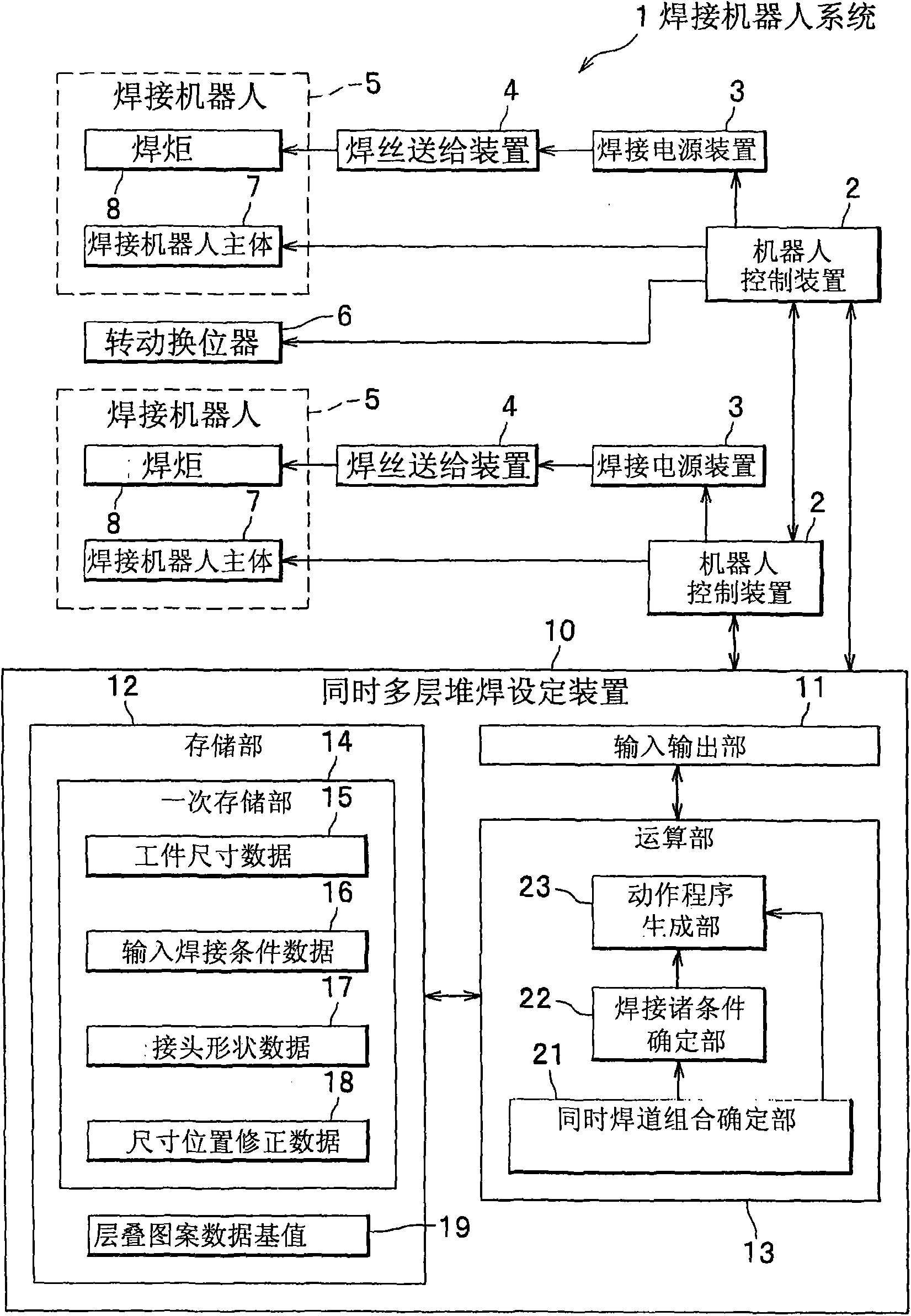
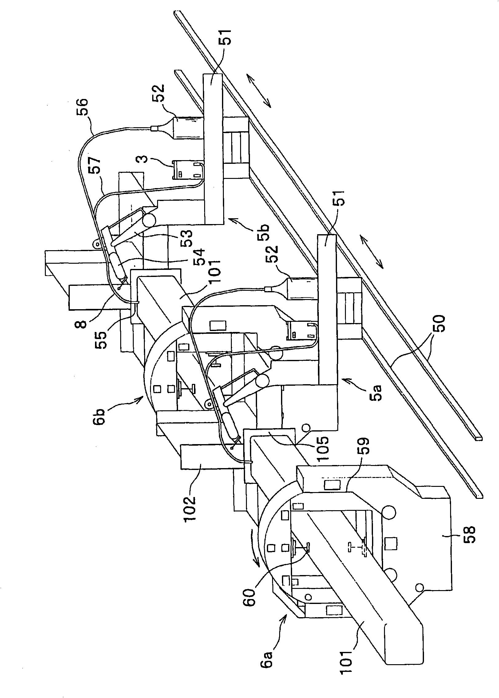
[0043] The welding robot system 1 of the embodiment of the present invention is as figure 1 As shown, it is equipped with a robot control device 2 , a welding power supply device 3 , a welding wire feeding device 4 , a welding robot 5 , a rotary positioner (positioner) 6 , and a setting device 10 for simultaneous multi-layer surfacing welding. Figure 12 shows a configuration example of a control block, which shows that in addition to setting the simultaneous multi-layer overlay welding in the welding robot system 1, it is also used to perform pre-processing for setting the simultaneous multi-layer overlay welding, pre-processing before welding, and The details of the control between each device of the welding process. Below, first, refer to figure 1 The outline of the welding robot system 1 and the outline of the configuration of the simultaneous multi-layer build-up welding setting device will be described. Figure 12 The detailed description will be mentioned later.

[0...

no. 2 approach

[0132] The simultaneous multilayer build-up welding setting device of the second embodiment differs from the first embodiment in that it performs adjustment processing of the joint position of the circular pipe during the simultaneous multilayer build-up welding. Therefore, the same structures as those of the simultaneous multi-layer build-up welding setting device 10 of the first embodiment are denoted by the same reference numerals, and descriptions thereof are appropriately omitted. First, the prerequisite conditions in the simultaneous multilayer build-up welding setting device (welding setting device) 10 of the second embodiment will be described.


PUM

PropertyMeasurementUnit
diameteraaaaaaaaaa

Abstract

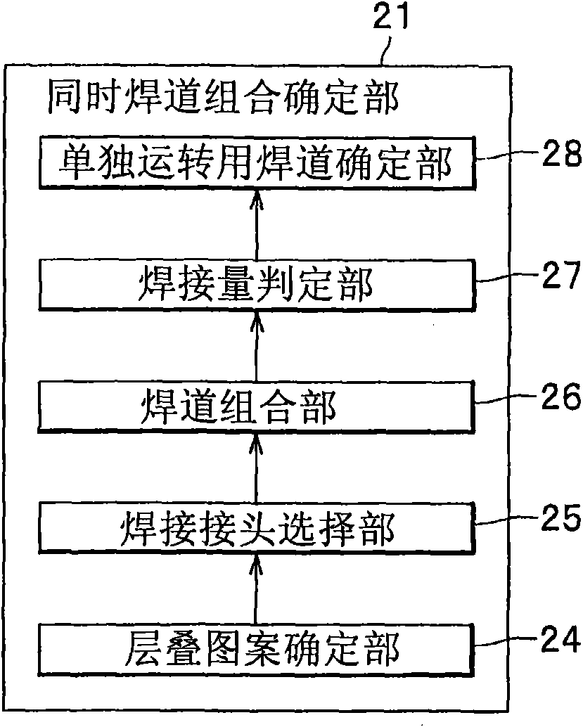
The invention provides a simultaneous multiple-layer welding setting device, comprising a cascading pattern determining part for determining the cascading pattern of a welding pass corresponding to joints of objects based on basic values of each input data and the cascading pattern data; a welding pass determining part for independently running which is used for determining the welding combination after excluding the welding pass with a large sectional area as the welding pass for independently running when the difference value of the sectional area of a deposited metal quantity is over the predetermined threshold value when combining the welding passes in the cascading pattern of two joints of the objects; a welding conditions determining part for determining each welding pass welding condition comprising current values corresponding to a welding wire feeding speed calculated based by an input welding condition and a seam forming position; and an action procedure generating part for generating a robot action procedure based on the determined welding conditions, and setting in a robot controlling device. The simultaneous multiple-layer welding setting device shortens the welding time of simultaneously welding a plurality of layers of a plurality of welding joints of a steel structure by two welding robots.

Description

technical field [0001] The invention relates to the technology of using multiple welding robots to simultaneously weld multiple welding joints of a steel structure in a welding robot system. Background technique [0002] At present, when installing a steel structure used as a building column, the temporarily welded column is kept horizontal by a rotary positioner, and the welding joint (simply referred to as a joint) of the steel structure is automatically welded by a welding robot . For steel structures used as pillars for construction, the diameter of the pillars is often, for example, 300 mm to 1 m or more. In addition, the length of the columns is generally several m to several tens of m. [0003] In addition, the welding conditions of steel structures are stipulated in accordance with Japanese Industrial Standards (JIS) and technical guidelines for steel frame engineering. The width (root gap) of the base of the joint is, for example, about several mm, and the height...

Claims


Application Information

Patent Timeline
Patent Type & Authority Applications(China)
IPC IPC(8): B23K9/095B23K9/12
Inventor 高田笃人松村浩史定广健次岸川浩久
Owner KOBE STEEL LTD
Learn More