
Prosthesis registering device

A technology for a prosthesis and a hip joint prosthesis, which is applied in the field of computer surgery navigation supporting devices, can solve the problems such as the limitation of the use of domestic hip joint prostheses, the inability to directly apply the navigation system, and the increase of the background workload, so as to achieve the change of maintenance operation mode, Improve the surgical effect, simple and practical effect

Inactive Publication Date: 2010-11-24
马若凡 +1
View PDF0 Cites 2 Cited by
  • Summary
  • Abstract
  • Description
  • Claims
  • Application Information

AI Technical Summary

Problems solved by technology

This method needs to record the virtual image in advance, and then compare and correlate the corresponding relationship between the actual prosthesis and the virtual image displacement. However, this method has its inherent defects: First, because new products are constantly emerging in the artificial hip joint market, The database of hip joint prosthesis types in the navigation system needs to be supplemented and updated regularly, which increases the workload of the background and reduces work efficiency; secondly, due to the individual differences and particularities of patients, many patients need to customize individualized hip Joint prostheses. In addition, there are some non-mainstream prosthetic products on the market. These prostheses that have not been pre-entered into the computer-aided system cannot be directly applied to the navigation system for surgical assistance; in addition, the current surgical navigation systems are The data information of domestic hip joint prosthesis is not included in the preset database of hip joint prosthesis produced by foreign manufacturers. Important factors in the development of the field of joint replacement

Method used


Image

  • Prosthesis registering device
  • Prosthesis registering device
  • Prosthesis registering device

Examples


Embodiment Construction

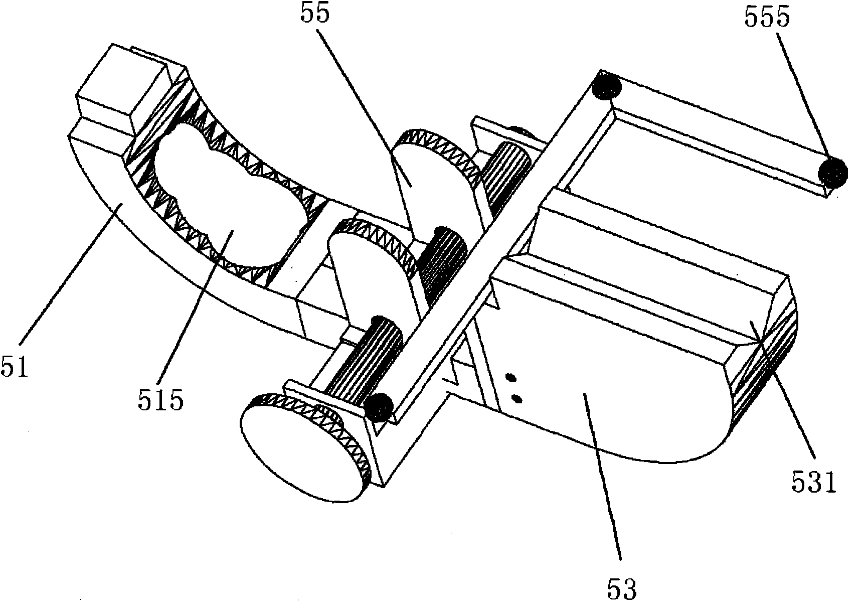
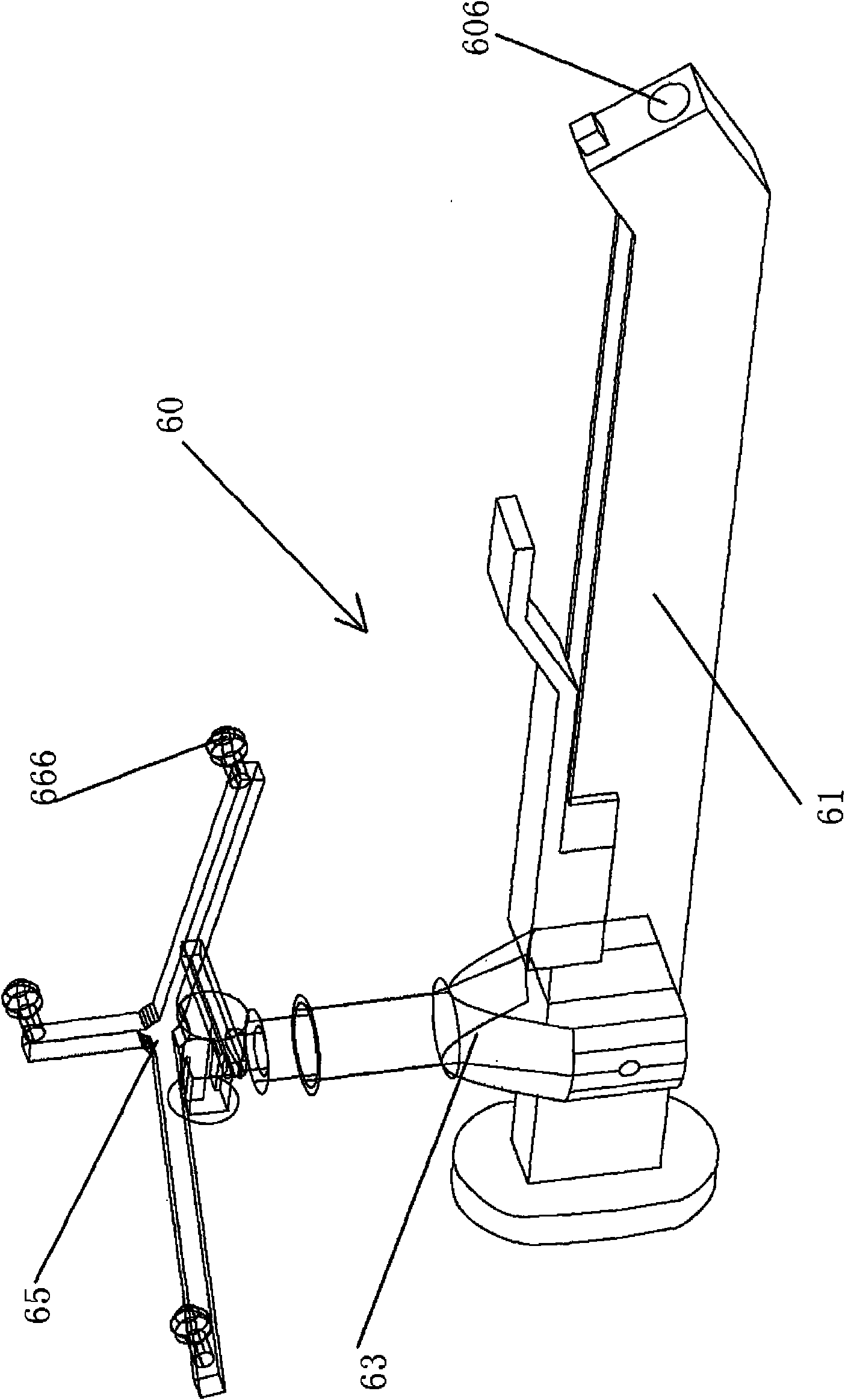
[0023] The prosthesis registration device of the present invention is used in conjunction with optical surgical navigation equipment, and is mainly applied to the registration and entry of hip joint prostheses. The prosthesis registration device is based on the principle of optical positioning, tracking and detection of spatial positions. The main components (such as the prosthesis gripper or the base of the prosthesis registration device) are equipped with optical signal reflection elements, which can place the prosthesis The information is transmitted to the optical navigation system, and the specific spatial position is determined through computer processing.

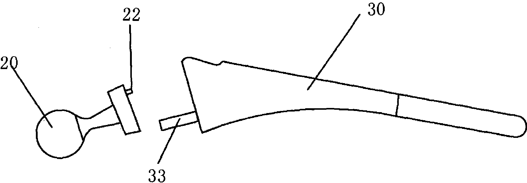
[0024] figure 1 Shown is a femoral head and neck prosthesis 20 and a femoral stem prosthesis 30, which the present invention allows for entry into a surgical navigation device. The femoral stem prosthesis 30 is provided with a clamping pin 33 towards the end of the femoral head and femoral neck prosthesis 20, and th...


PUM


Abstract

The invention discloses a prosthesis registering device which is used for registering and entering all types of hip joint prostheses in a surgical navigation system. The prosthesis registering device comprises a base and a femoral stem prosthesis holder or a mortar cup prosthesis holder matched with the base, wherein the base comprises a rear seat for containing a femoral stem prosthesis, a curved arm part for containing a femoral head prosthesis and a femoral neck prosthesis, and a clamping part which is connected between the rear seat and the curved arm part and is used for fixedly clamping the femoral stem prosthesis; and at least three optical reflection spheres which are not positioned on the same straight line are respectively arranged on the femoral stem prosthesis holder, the mortar cup prosthesis holder and the base. The invention can enable all types of hip joint prostheses to be entered and registered into a computer-aided navigation system in real time, and has wide application range, simple structure and simple and convenient operation.

Description

technical field [0001] The present invention relates to a computer surgical navigation matching device, more specifically, the present invention relates to a hip joint prosthesis registration device matching computer optical surgical navigation. Background technique [0002] Before the emergence of computer-assisted surgical navigation, prosthesis replacement surgery mainly relied on the operator's experience and visual inspection for positioning. The operation was difficult and the surgical effect was not ideal. The emergence of computer-aided surgical navigation system can be described as a leap forward in the field of artificial joint replacement assisted positioning. The system uses an optical positioning system as a detection instrument, and the supporting computer system interface allows doctors to use stereoscopic sensing and directional tools to perform navigation operations for artificial hip replacement based on two-dimensional or three-dimensional simulation image...

Claims


Application Information

Patent Timeline
IPC IPC(8): A61B19/00A61B5/00G01B11/00G01B11/24A61B34/20A61F2/32
Inventor 马若凡廖广军许杰戚其丰
Owner 马若凡
Learn More