
High frequency range and high power frequency hopping filter

A filter and high-power technology, applied in the field of frequency hopping filters, can solve the problems of large product volume, poor selectivity in high frequency band, large insertion loss, etc., and achieve good filter selectivity, excellent filtering effect, and insertion loss. small effect

Inactive Publication Date: 2010-11-17
广州市圣大电子有限公司
View PDF3 Cites 0 Cited by
  • Summary
  • Abstract
  • Description
  • Claims
  • Application Information

AI Technical Summary

Problems solved by technology

[0002] High-power frequency-hopping filters belong to band-pass filters. The disadvantages of current high-power frequency-hopping filter designs are large insertion loss, poor filter selectivity, and poor heat dissipation of components, resulting in short working life; selectivity for high-frequency bands Not good, the sensitivity of the filtered signal is not high, and the integration of high-power frequency-hopping filters is not high, the product is bulky, and the manufacturing cost is high

Method used


Image

  • High frequency range and high power frequency hopping filter
  • High frequency range and high power frequency hopping filter
  • High frequency range and high power frequency hopping filter

Examples


Embodiment Construction

[0014] In order to make the purpose, technical solution and advantages of the present invention clearer, the present invention will be further described in detail below in conjunction with the accompanying drawings.

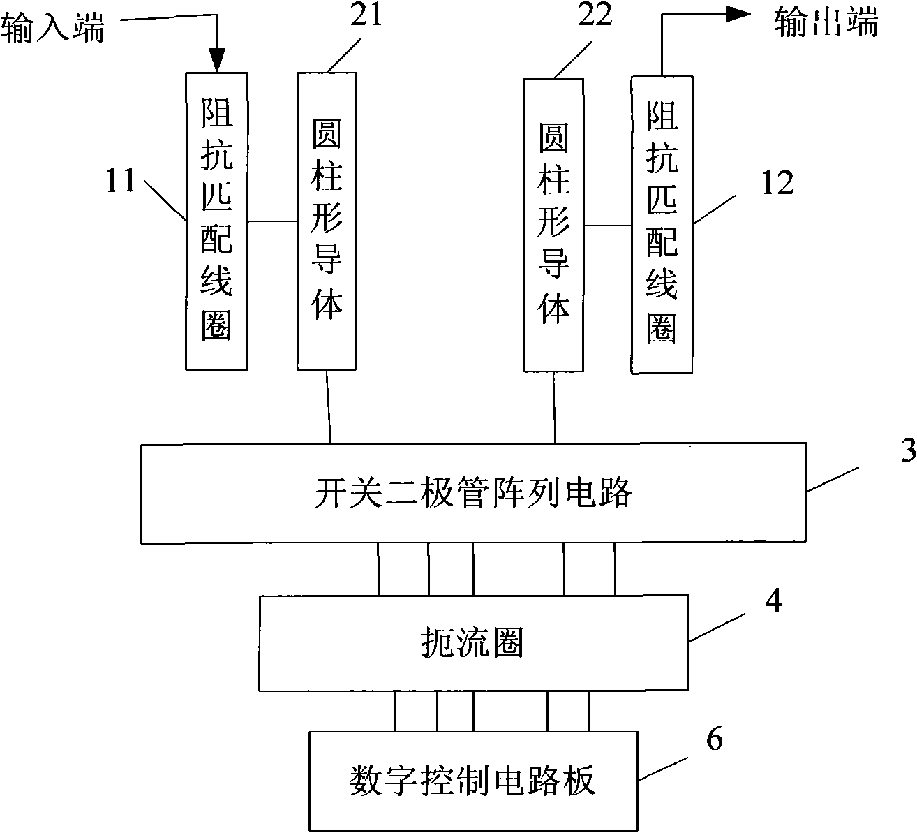
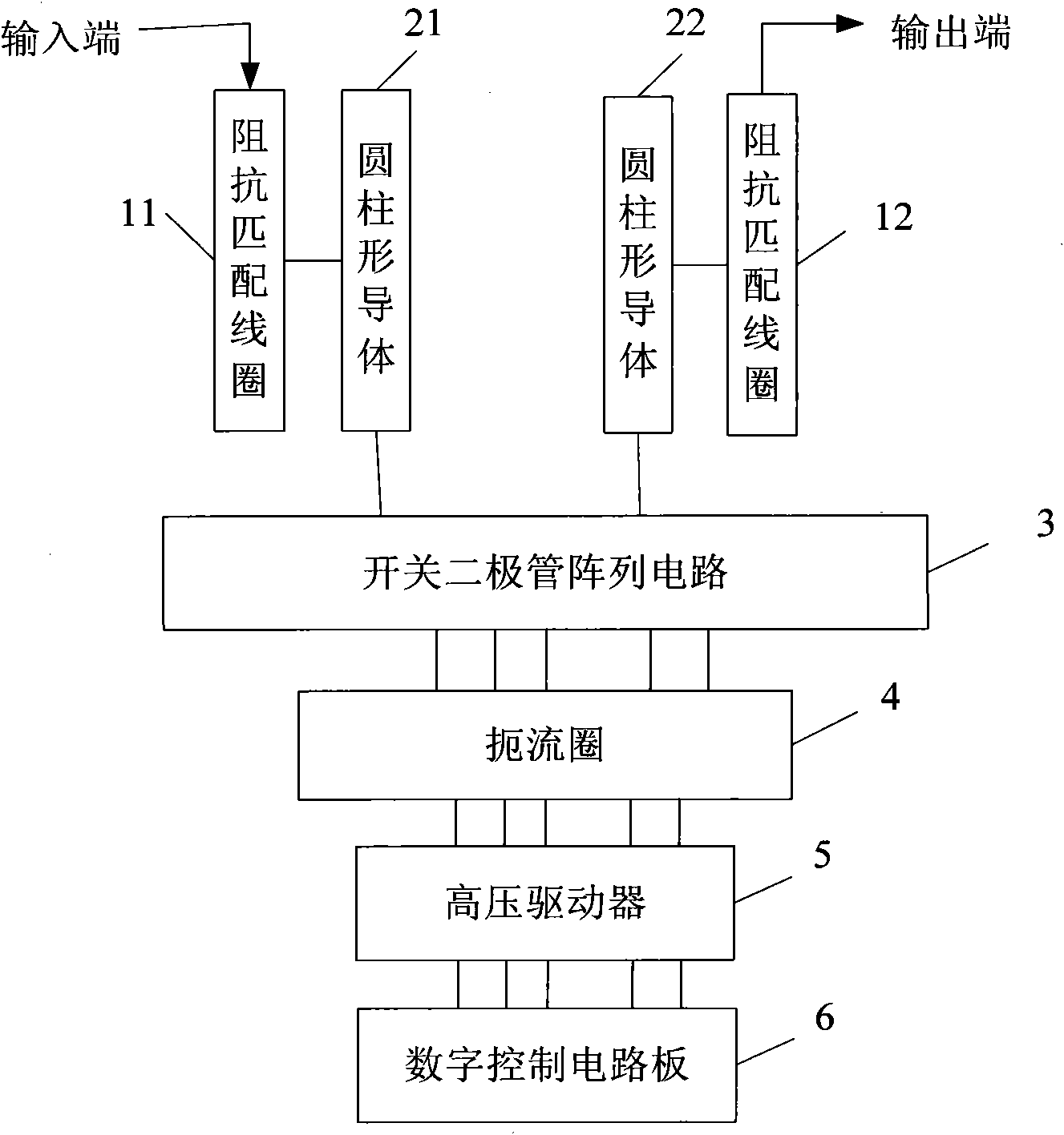
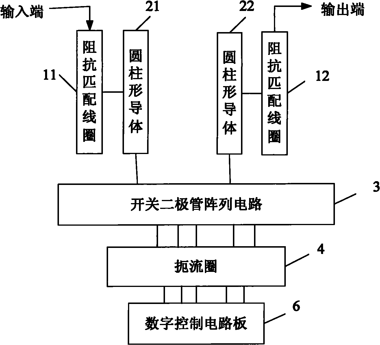
[0015] Such as figure 1 As shown, Embodiment 1 of the present invention provides a high-frequency high-power frequency-hopping filter. In the metal casing, the cavity structure resonator is connected to the switching diode array circuit 3, the choke coil 4 and the frequency-hopping filter for controlling the frequency-hopping filter in sequence. The digital control circuit board 6 is connected; the cavity structure resonator is composed of two cylindrical conductors with a length of 1 / 4 wavelength and two impedance matching coils arranged in an independent cavity. Specifically, the signal input end of the filter is sequentially connected to the impedance matching coil 11 , the cylindrical conductor 21 and the switch diode array circuit 3 . The input signal is co...


PUM


Abstract

The invention discloses a high frequency range and high power frequency hopping filter. In a metal shell, a resonator in a cavity structure is sequentially connected with a switching diode array circuit, a choke coil and a digital control circuit board for controlling frequency hopping filtering and consists of a first cylindrical conductor, a second cylindrical conductor, a first impedance matching coil and a second impedance matching coil which are arranged in independent cavities and have the length of a quarter wavelength. By adopting the resonator in the special cavity structure, the high frequency range and high power frequency hopping filter has excellent filtering effect in the high frequency range, favorable filtering selectivity and less insertion loss. A high power switching diode array with a large heating value is welded on a silver-plated copper plate, and the silver-plated copper plate is connected with a heat conducting plate of the metal shell, thereby the heat dispersion is faster.

Description

technical field [0001] The invention relates to the field of electronic communication, in particular to a frequency hopping filter. Background technique [0002] High-power frequency-hopping filters belong to band-pass filters. The disadvantages of current high-power frequency-hopping filter designs are large insertion loss, poor filter selectivity, and poor heat dissipation of components, resulting in short working life; selectivity for high-frequency bands Not good, the sensitivity of the filtered signal is not high, and the integration of the high-power frequency hopping filter is not high, the product is bulky, and the manufacturing cost is high. Contents of the invention [0003] The embodiment of the present invention provides a high-frequency high-power frequency-hopping filter, which adopts a resonator with a unique cavity structure, has excellent filtering effect, small insertion loss, and high stability. [0004] The embodiment of the present invention provides ...

Claims


Application Information

Patent Timeline
IPC IPC(8): H03H9/46
Inventor 张洪磊屈绳勇
Owner 广州市圣大电子有限公司
Learn More