
Spring fatigue testing equipment and testing method thereof

A technology of fatigue test and test method, which is applied in the testing of mechanical components, testing of machine/structural components, testing the strength of materials by applying repeated force/pulsation force, etc. Load and other problems, achieve simple and reliable detection, realize unmanned operation, and reduce power output

Inactive Publication Date: 2010-11-10
JAPHL POWERTRAIN SYST
View PDF5 Cites 28 Cited by
  • Summary
  • Abstract
  • Description
  • Claims
  • Application Information

AI Technical Summary

Problems solved by technology

This requires that the planar scroll spring can be tightened and unrolled within a specified time. The existing scroll spring fatigue test equipment has a wide variety of detection methods, such as realizing the tightness of the scroll spring through the reciprocating action of the hydraulic cylinder, The way of the forward and reverse of the servo motor realizes the tightness of the scroll spring, etc., but these methods have some shortcomings: 1. The response time of the hydraulic cylinder and the servo motor is slow, resulting in a long time to complete the fatigue test. It takes 2 to 3 months for the cylinder to complete the fatigue test of 10 million times
Other equipment even takes 4 months to complete; 2. The total load torque is large and the efficiency is low
Since only one spring can be detected at a time, the spring can only work once per rotation of the servo motor, resulting in low test efficiency
If multiple springs need to be detected, the total load torque acting on the power equipment is equal to the superposition of several springs, which increases the load; 3. The equipment requires power equipment such as hydraulic cylinder mechanisms and servo motors, and a large amount of heat is generated during the work of the springs. , need cooling equipment
These devices and mechanisms cause an increase in cost; 4. The versatility of these devices is poor, such as hydraulic cylinders that cannot change the pre-tightening angle and servo motors that need to change the current setting to achieve it, making the versatility poor

Method used


Image

  • Spring fatigue testing equipment and testing method thereof
  • Spring fatigue testing equipment and testing method thereof
  • Spring fatigue testing equipment and testing method thereof

Examples


Embodiment Construction

[0037] Below with reference to the accompanying drawings, through the description of the embodiments, the specific embodiments of the present invention, such as the shape, structure, mutual position and connection relationship between the various parts, the role and working principle of the various parts, etc., will be further described. Detailed instructions:

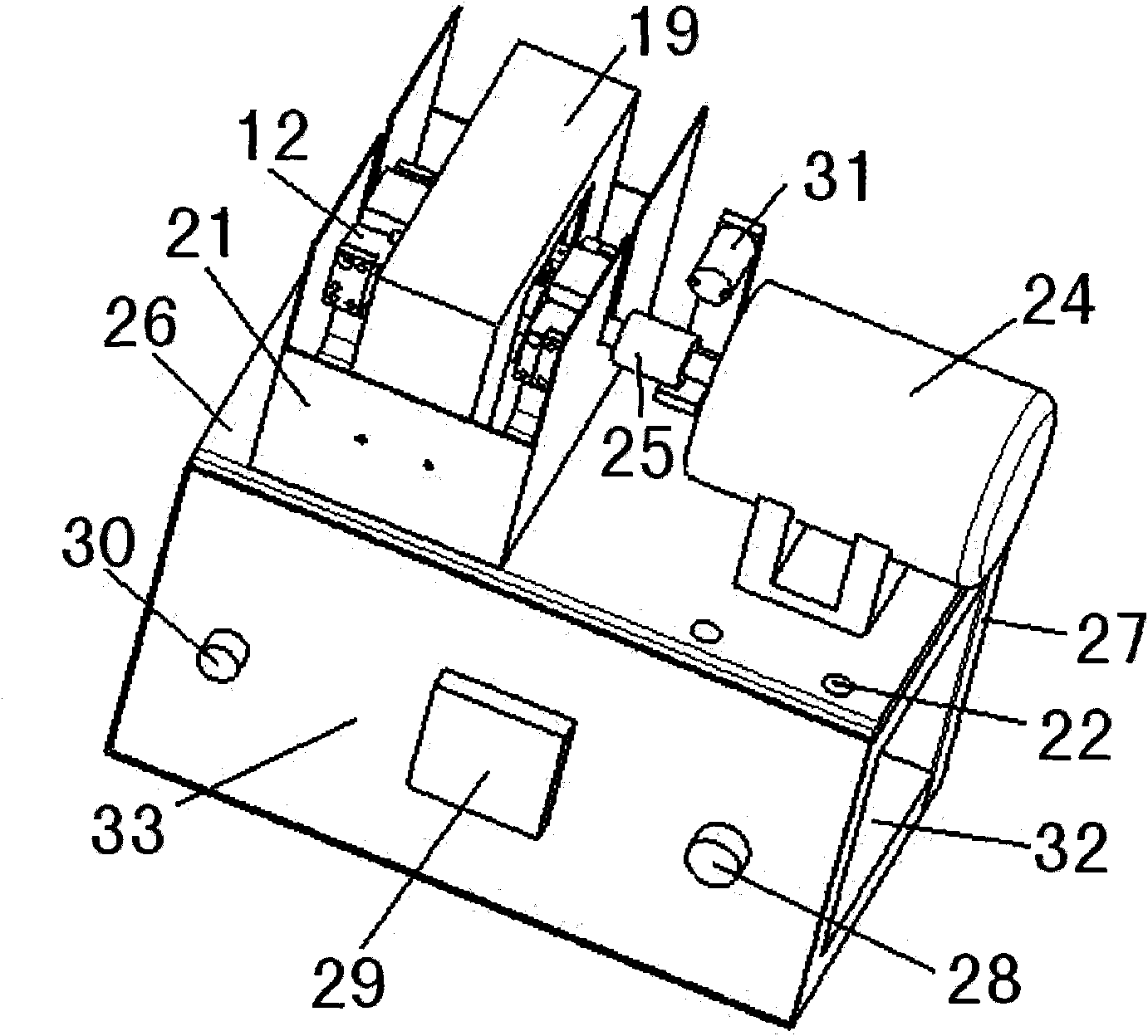
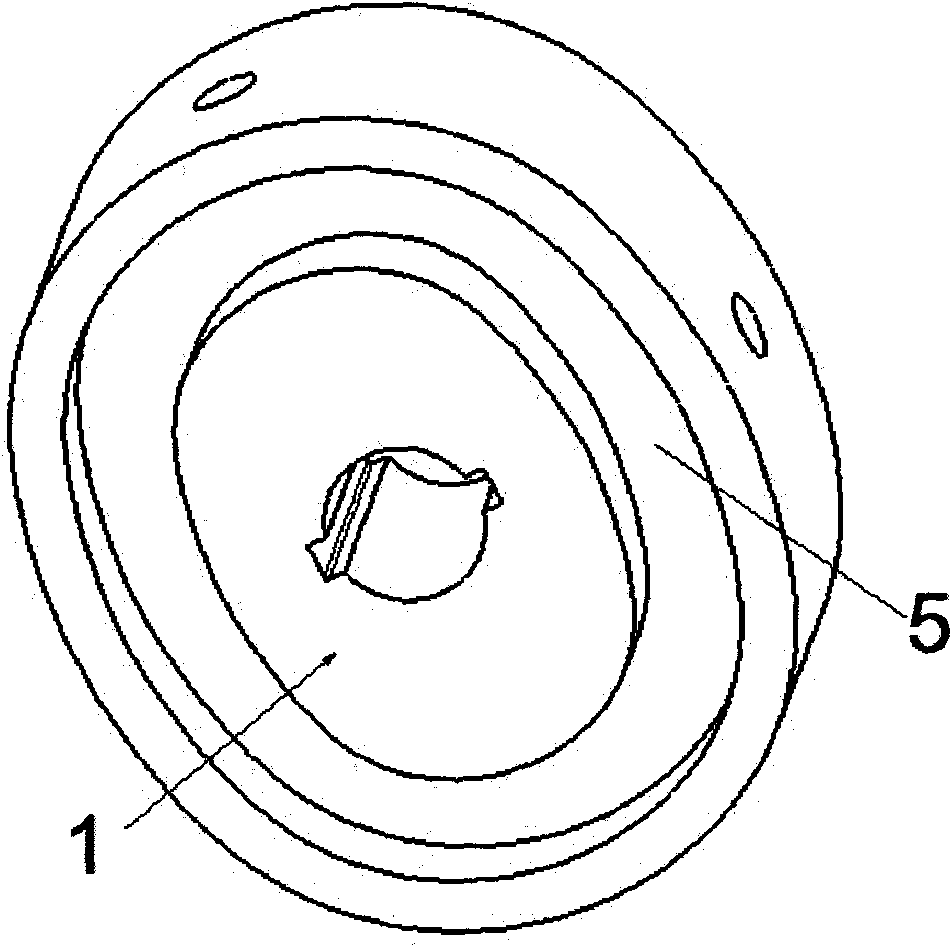
[0038] as attached figure 1As shown, the present invention is a kind of spring fatigue test equipment, and described spring fatigue test equipment comprises cam disc 1, transmission shaft 2, rocker arm 9, locking block 12, second rocker arm shaft 14, slide block 20, support 23, the motor 24, the control switch 28, the bracket 23 is set as an inverted "T" structure, the cam disc 1 is set on the transmission shaft 2, and the side of the cam disc 1 is provided with grooves along the two sides of the cam disc 1. Slider type wire slot 5, drive shaft 2 is connected with bracket 23; locking block 12 is fixed on the side of b...


PUM


Abstract

The invention provides spring fatigue testing equipment applied to the field of testing, and also relates to a testing method of the equipment. A bracket (23) of the spring fatigue testing equipment has a reverse T-shaped structure; a cam disk (1) is arranged on a transmission shaft (2); the side face of the cam disk (1) is provided with a slide block type slot (5); a locking block (12) is fixed to a side edge of the bracket (23); a rocker shaft (10) passes through a big hole (34) and a circular hole (36); another rocker shaft (14) passes through a small hole (35); a small end (8) of the rocker shaft is propped against the locking block (12); one end of the rocker shaft (14) opposite to the small end (8) of the rocker shaft is connected with a slide block (20); the slide block (20) is embedded in the slot (5); the transmission shaft (2) is connected with a motor (24); and the motor (24) is connected with a control switch (28). The invention realizes high-efficiency testing of the spring fatigue equipment, greatly reduces the required power output and also realizes unmanned operation.

Description

technical field [0001] The present invention relates to the field of testing equipment, more specifically, relates to a spring fatigue testing equipment, and the present invention also relates to a testing method of the testing equipment. Background technique [0002] The planar scroll spring is mainly used to withstand the bending torque, store energy through the spring's own torsion, and release energy as needed to achieve action. This requires that the planar scroll spring can be tightened and unrolled within a specified time. The existing scroll spring fatigue test equipment has a wide variety of detection methods, such as realizing the tightness of the scroll spring through the reciprocating action of the hydraulic cylinder, The way of the forward and reverse of the servo motor realizes the tightness of the scroll spring, etc., but these methods have some shortcomings: 1. The response time of the hydraulic cylinder and the servo motor is slow, resulting in a long time t...

Claims


Application Information

Patent Timeline
IPC IPC(8): G01M13/00G01N3/32
Inventor 王震曹志诚李雪涛范礼
Owner JAPHL POWERTRAIN SYST
Learn More