
Hydrogen supplying device

A technology for supplying hydrogen and hydrides, which is applied in the production of hydrogen, fuel cell additives, fuel cells, etc., and can solve the problems of reduced efficiency, high price, and inability to shake up and down, left and right, etc.

Inactive Publication Date: 2010-11-03
IND TECH RES INST
View PDF1 Cites 10 Cited by
  • Summary
  • Abstract
  • Description
  • Claims
  • Application Information

AI Technical Summary

Problems solved by technology

When using solid hydrogen fuel (catalyst plus sodium borohydride), it is necessary to add water to make it react to generate hydrogen, as shown in Formula 1, which will encounter two huge problems: one is how to maintain a stable hydrogen supply rate? At present, complex mechanical designs are used internationally to maintain a stable hydrogen supply rate.
On the other hand, the method of adding water to generate hydrogen gas with solid hydrogen fuel (catalyst plus sodium borohydride) will encounter another problem: it can only be used in one direction, and it cannot be used when shaking up and down
Because when shaking up and down, the liquid water will be carried to the fuel cell by the hydrogen, causing the performance of the fuel cell to decline and making it impossible to carry
At present, the solution adopted in the world is to use hydrophobic gas-liquid separation membrane to achieve the purpose of breathable and water-repellent, but its disadvantage is that it is expensive, resulting in increased costs
In addition, the gas-liquid separation membrane cannot completely block liquid water, and the pressure caused by hydrogen generation will also squeeze a small amount of water to the fuel cell and reduce its efficiency

Method used


Image

  • Hydrogen supplying device
  • Hydrogen supplying device
  • Hydrogen supplying device

Examples


Embodiment 1

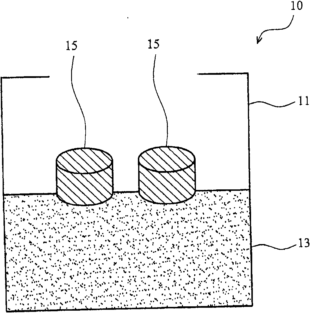
[0028] Take 1g of water-absorbing polymer sodium polyacrylate and place it in a container, and add 25g of water. After standing for 10 minutes, a non-flowing hydrogel was formed.

[0029] With reference to the method of No. 98108205 of Chinese Taiwan patent application number, get solid hydride (NaBH 4 ), catalyst (Co 2+ / IR-120) after high-speed ball milling, then add silicone rubber to form flexible solid hydrogen fuel. Then, the above-mentioned solid hydrogen fuel was formed into an ingot by a granulator, and each ingot of the solid hydrogen fuel contained 1 g of solid hydride, 0.1 g of catalyst, and 0.1 g of silicone rubber.

[0030] After placing two ingots of solid hydrogen fuel on the above water gel, the solid hydrogen fuel will absorb water and react to form hydrogen gas. After measurement, the relationship between hydrogen desorption rate and time is shown in Figure 4 shown.

Embodiment 2

[0032] Take 0.5g of sodium polyacrylate and evenly spread it on the water-absorbent cotton material (5cm*13cm*0.05cm, ultra-thin cosmetic cotton KK-II purchased from Yani International Co., Ltd.) to form a sheet-shaped water-absorbent material.

[0033] With reference to the method of No. 98108205 of Chinese Taiwan patent application number, get solid hydride (NaBH 4 ), catalyst (Co 2+ / IR-120) after high-speed ball milling, then add silicone rubber to form flexible solid hydrogen fuel. Next, the above-mentioned solid hydrogen fuel is pressed into sheets and then cut to form a sheet-shaped solid hydrogen fuel (4cm*11cm*0.1cm).

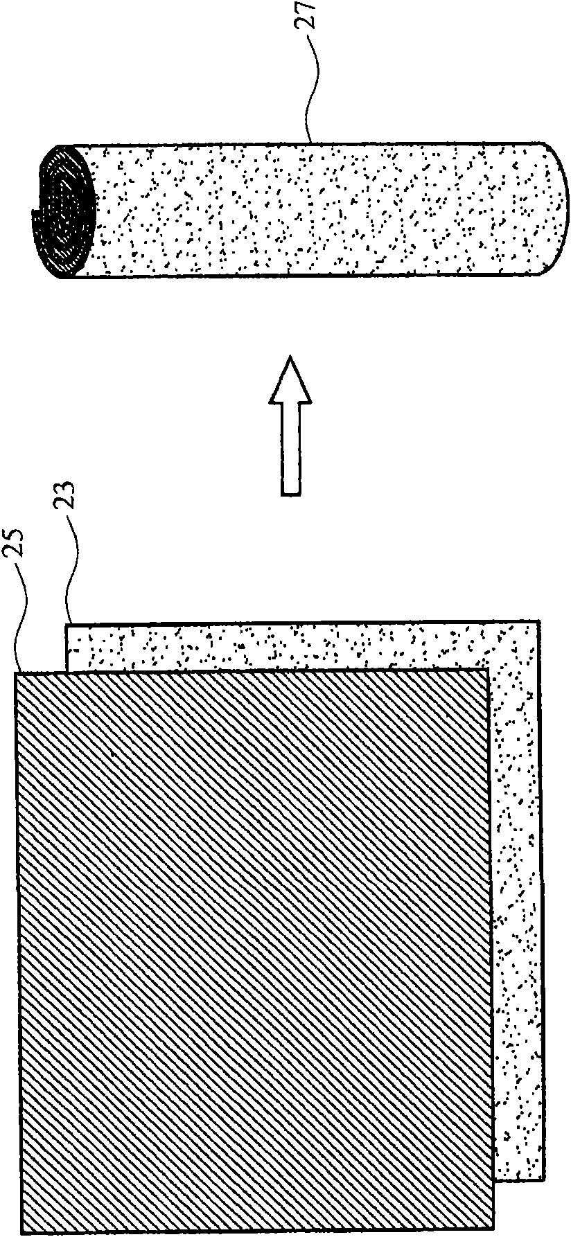
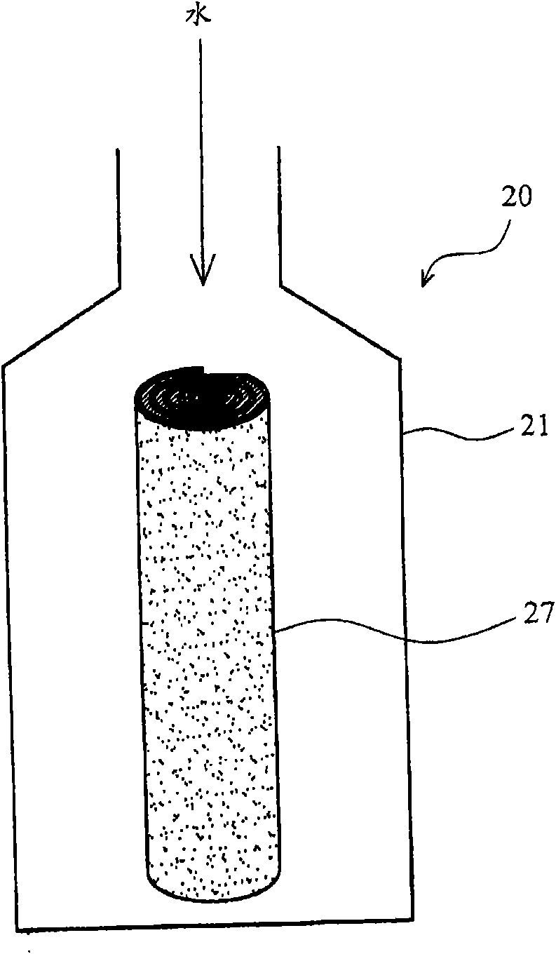
[0034] The sheet-shaped water-absorbing material and the sheet-shaped solid hydrogen fuel are laminated and rolled into a rod, and the rod is placed in a container. After adding 20g of water to the container, the water-absorbent material quickly absorbs water. After standing for five minutes, pour out the excess water and measure the hydrogen releas...


PUM


Abstract

The invention relates to a hydrogen supplying device which enables water to be in a non-flowing state by utilizing a water-absorbent macromolecule and accelerates water absorption by further blending the water-absorbent macromolecule with a water-absorbent cotton material. The stable hydrogen supplying device can be formed by blending the water-absorbent cotton material with a solid hydrogen fuel, and even if the hydrogen supplying device is overturned or laterally laid, the hydrogen supplying device can not enable a fuel cell to be reduced in property and even unable to generate electricity because liquid water flows into the fuel cell and blocks an MEA (membrane electrode assembly) membrane.

Description

technical field [0001] The invention relates to a hydrogen supply device, in particular to the application of the hydrogen supply device in a fuel cell. Background technique [0002] Recently, the demand for many portable energy sources, such as portable computers, walkmans, cameras, walkmans and other digital devices, requires a cheap, long-term power supply, small size, light weight, and can be used in various environments battery. Although known fuel cells are economical and long-lasting, they cannot be widely used in various portable products due to the limitation of hydrogen fuel supply. Therefore, solving the problem of hydrogen fuel supply will be the trend of small portable hydrogen energy power generation systems in the future. The supply of hydrogen fuel must meet the principles of cheapness, convenience, small size, light weight, and stable hydrogen supply rate. The biggest advantage of using chemical hydrogen storage materials as a source of hydrogen is its hi...

Claims


Application Information

Patent Timeline
Patent Type & Authority Applications(China)
IPC IPC(8): H01M8/04C01B3/06H01M8/04089
CPCY02E60/362Y02E60/50Y02E60/36
Inventor 薛展立谷杰人许雅意蔡幸芬太原丽子洪剑长陈政严郑名山曹芳海
Owner IND TECH RES INST
Learn More