
Laser projector

一种激光投影机、激光的技术,应用在光学、光学元件、仪器等方向,能够解决无法检测反射光、无法进行图像的修正、显示图像画质劣化等问题

Inactive Publication Date: 2010-11-03
FUNAI ELECTRIC CO LTD
View PDF5 Cites 16 Cited by
  • Summary
  • Abstract
  • Description
  • Claims
  • Application Information

AI Technical Summary

Problems solved by technology

[0008] However, in the case of using the above-mentioned prior art, there is a problem that information loss may occur by optical image processing, which may degrade the image quality of the displayed image.
[0009] In addition, in the case of using the above-mentioned Patent Document 1, for example, the irradiation angle of the laser beam irradiated to the projection screen is small, and the reflected light reflected by the laser beam on the projection screen does not return to the projector side. The light receiving part cannot detect reflected light, and if the distance from the projector to the projection screen cannot be measured (measured), image correction processing may not be possible

Method used


Image

  • Laser projector
  • Laser projector
  • Laser projector

Examples


Embodiment Construction

[0052] Hereinafter, embodiments of the present invention will be described with reference to the drawings. In addition, the scope of the invention is not limited to the illustrated examples.

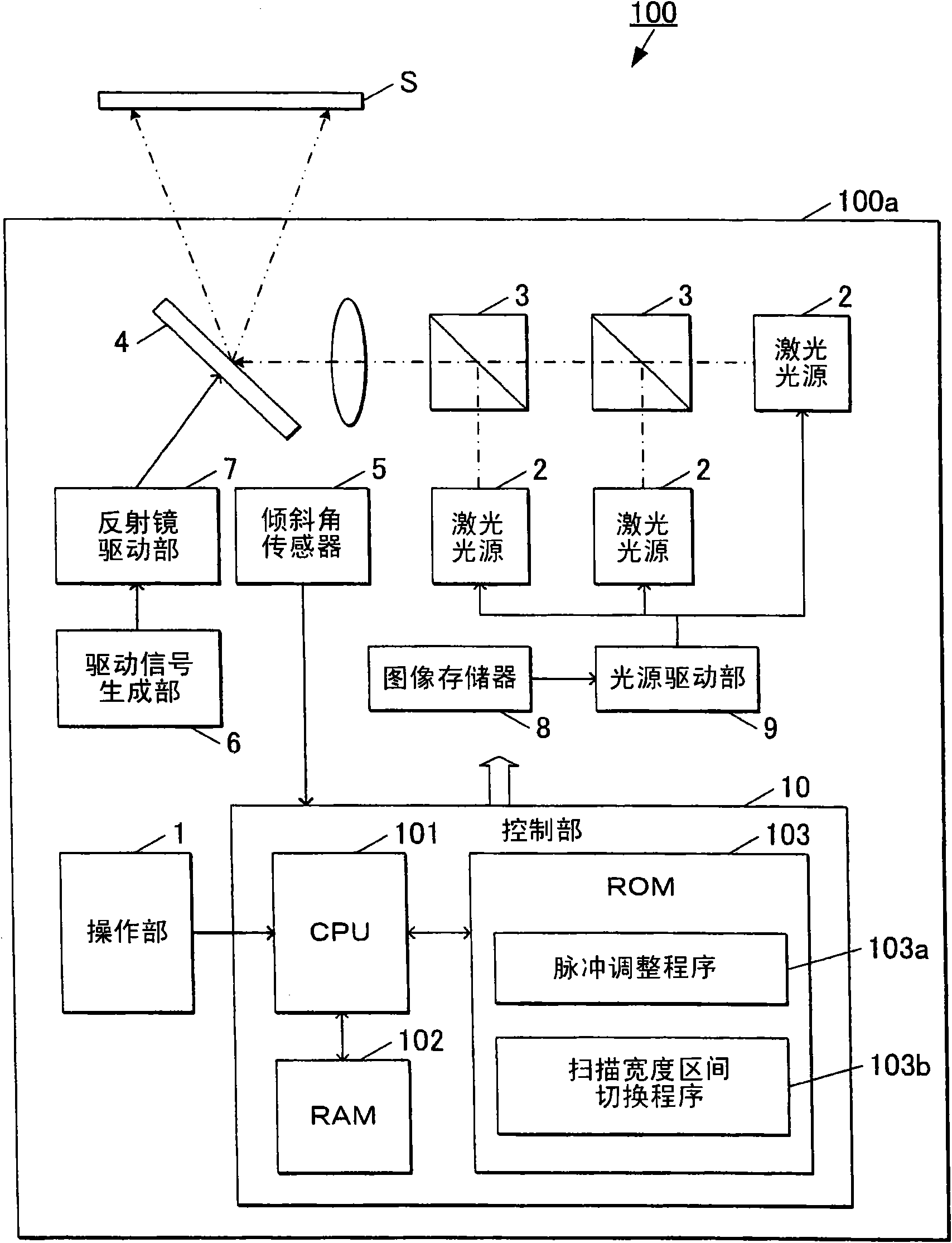
[0053] Such as figure 1 As shown, the laser projector 100 has in the frame 100a: an operation part 1, a laser light source 2 for irradiating laser light, a mirror part 3 for combining the laser light from the laser light source 2, and a laser beam from the laser light source 2. The electromagnetically driven scanning mirror 4 for scanning the laser beam on the projection screen S as the projection surface, the inclination angle sensor 5 for detecting the inclination angle of the laser projector 100 relative to the projection screen S, and the drive signal for generating a predetermined frequency The driving signal generating part 6, the mirror driving part 7 for driving the electromagnetically driven scanning mirror 4 based on the driving signal generated by the driving signal generatin...


PUM


Abstract

The invention provides a laser projector capable of more reliably correcting the projection image. The laser projector (100) adjusts the left-right swing width of an electromagnetic drive type scan mirror (4) from the first swing width to the second swing width in a projection interval (a) for forming the image on a projection screen (S), thus the projection image on the projection screen (S) is corrected into a rectangle. Especially after moving to a later-state interval (b2) before the projection interval (a) for projecting the image on the projection screen (S), the left-right swing width of the electromagnetic drive type scan mirror (4) is kept be the first swing width corresponding with the width at the initial end of the projection interval (a), the left-right swing width of the electromagnetic drive type scan mirror (4) is easily adjusted from the first swing width to the second swing width to project the corrected image, thus image is more reliably corrected and projected.

Description

technical field [0001] The present invention relates to a laser projector that scans a projection surface with light from a laser light source to display images. Background technique [0002] As a laser projector using laser light as a light source, for example, a technique is known in which laser light from a laser light source is reflected by a resonator mirror in biaxial directions to irradiate a projection screen to display an image. [0003] For the laser light irradiated from the laser projector to the projection screen, scanning is performed while changing the irradiation angle by using a mirror, so trapezoidal deformation may occur: the longer the distance from the projector, the more difficult the image projected on the projection screen will be. become bigger. [0004] As a technique for correcting such trapezoidal deformation, a technique of correcting an image into a rectangle by performing image processing on a projector is generally used. [0005] In addition...

Claims


Application Information

Patent Timeline
Patent Type & Authority Applications(China)
IPC IPC(8): G03B21/00G03B21/14G02B26/10
CPCG02B26/105G02B26/0833H04N9/3129
Inventor 近冈笃彦平野敦也西冈谦西垣宏
Owner FUNAI ELECTRIC CO LTD
Learn More