
Aluminum frame pneumatic engaging device for solar module

An occlusal device, aluminum frame technology, applied in electrical components, semiconductor devices, climate sustainability, etc., can solve problems such as easy cracks, short aluminum frame and long aluminum frame cracks, corner codes and long and short frames easy to loosen, etc. Achieve the effect of reducing cracks, improving sealing performance and connection firmness

Active Publication Date: 2014-09-10
EGING PHOTOVOLTAIC TECHNOLOGY CO LTD
View PDF6 Cites 0 Cited by
  • Summary
  • Abstract
  • Description
  • Claims
  • Application Information

AI Technical Summary

Problems solved by technology

In the existing packaging process, if the size of the corner code does not meet the predetermined requirements, it will easily loosen between the corner code and the long and short frames, resulting in cracks at the connection between the short aluminum frame and the long aluminum frame, especially for solar cell modules After long-term exposure under natural conditions, the adhesive force of the sealant will decrease, which will lead to a decrease in the bonding force between the frame and the battery laminate, and cracks are more likely to occur at the joint between the short aluminum frame and the long aluminum frame
After careful observation and analysis by the applicant, the main reason for the above-mentioned defects is that the connection between the corner bracket and the long aluminum frame is unreliable. The existing technology can only punch out tightening dimples on the inner surface of the short aluminum frame, but the long aluminum frame and the serrated pins of the corner codes cannot punch the tightening dimples. Therefore, the four connecting corners of the solar cell module are the The connection point is also a place where cracks are prone to occur, and the connection between the long aluminum frame and the corner bracket is the main cause of cracks

Method used


Image

  • Aluminum frame pneumatic engaging device for solar module
  • Aluminum frame pneumatic engaging device for solar module
  • Aluminum frame pneumatic engaging device for solar module

Examples


Embodiment Construction

[0015] The specific embodiment of the present invention is described in detail below in conjunction with accompanying drawing:

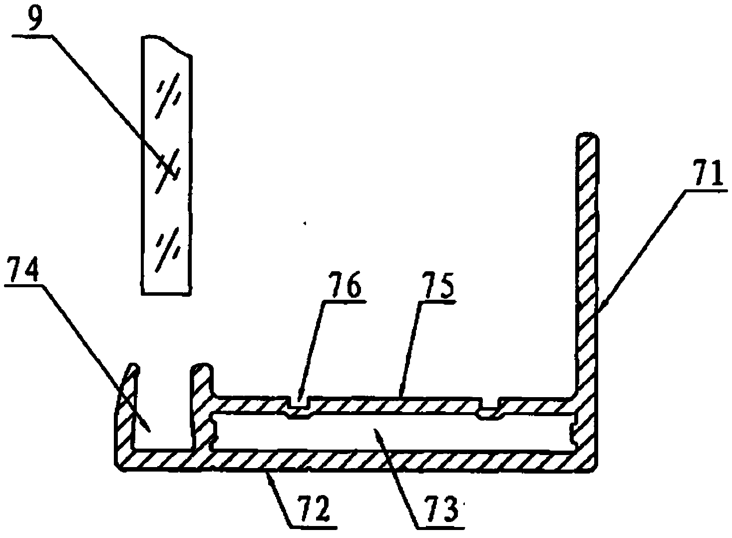
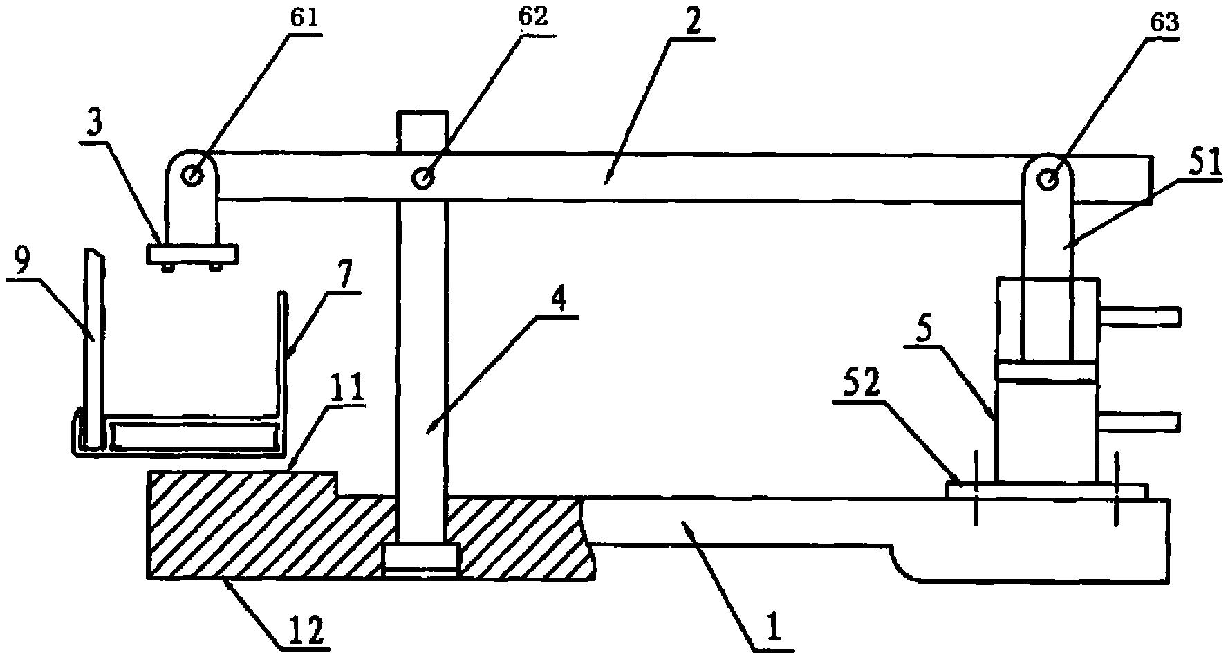
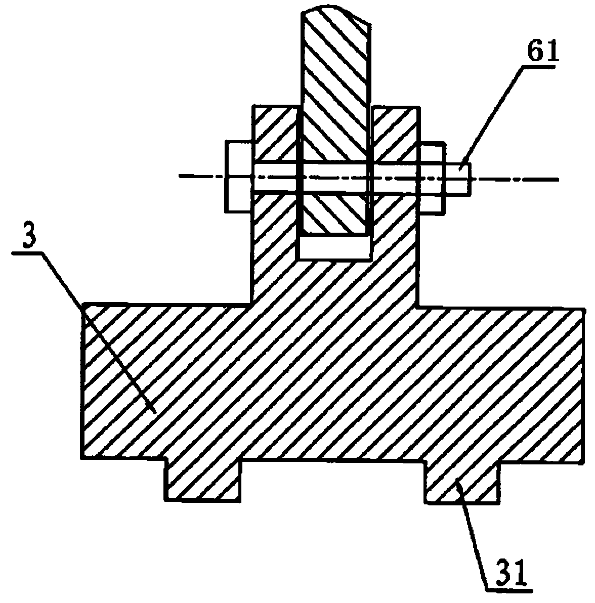
[0016] The aluminum frame of the solar cell module is pneumatically punched and engaged, such as figure 1 , figure 2 As shown, it includes a base plate 1, a lever 2, a stamping die head 3, a pressure bearing column 4 and a pressure cylinder 5, the pressure bearing column 4 is fixed on the base plate 1, and the stamping die head 3 is hinged through a first pin shaft 61 On the left end of the lever 2, a pressure bearing platform 11 is arranged on the left end 12 of the base plate. The width of the pressure bearing platform 11 is equivalent to the width of the outer surface 72 of the aluminum frame 7. The pin 62 is hinged, the piston rod 51 of the pressure cylinder 5 is hinged with the right end of the lever 2 through the third pin 63, the cylinder body 52 of the pressure cylinder 5 is fixed on the base plate 1, and the pressure cylinder 5 is controll...


PUM


Abstract

The invention provides an aluminum frame pneumatic engaging device for a solar module. The device comprises a base plate, a lever, a stamping head, a loaded column and a pressurizing cylinder, wherein the stamping head is hinged with the left end of the lever; the lever is hinged with the upper end of the loaded column; a piston rod of the pressurizing cylinder is hinged with the right end of the lever; the body of the pressurizing cylinder is fixed on the base plate; the pressurizing cylinder is controlled by the pneumatic control device to act; and a convex body structure is arranged on the lower end surface of the stamping head. After the solar cell module is encapsulated with adhesive, the long aluminum frame is subjected to tightening and engaging treatment by the module, so that the long aluminum frame and the short aluminum frame are both firmly engaged with zigzag angles to form a whole, which can greatly reduce the phenomenon that cracks are generated among aluminum frames after the solar cell module is used outdoor for long time, and improve the sealing performance and connecting firmness of the solar cell module.

Description

technical field [0001] The invention relates to a packaging tool for a solar battery module, in particular to a packaging and engaging device for an aluminum frame of a solar battery module. Background technique [0002] The solar panel is the core part of the solar power generation system, and it is also the most valuable part of the solar power generation system. Its function is to convert solar energy into electrical energy. The battery laminate must be packaged and protected with a frame during outdoor applications. If the battery laminate is not well sealed, encountering rain or working in a high-humidity environment for a long time, it will accelerate the damage of the battery laminate and cause solar energy The battery board cannot work properly, and the basic requirement of the package is to be sealed. [0003] The solar cell module is glued and packaged with an aluminum frame. The long aluminum frame and the short aluminum frame are connected by corners with jagged...

Claims


Application Information

Patent Timeline
IPC IPC(8): H01L31/18
CPCY02P70/50
Inventor 陈鑫
Owner EGING PHOTOVOLTAIC TECHNOLOGY CO LTD
Learn More