Ultrasonic soldering flux coating process and device

A technology for coating device and flux, which is applied to devices for coating liquid on surfaces, spray devices, liquid spray devices, etc., which can solve the problems of complicated operation, complicated internal mechanism, and the size and speed of spray volume are easily affected by flux flow rate. The size and flow rate of the impact of other issues, to achieve the effect of strong adhesion and good wettability

Inactive Publication Date: 2010-10-27
View PDF6 Cites 6 Cited by
  • Summary
  • Abstract
  • Description
  • Claims
  • Application Information

AI Technical Summary

Problems solved by technology

Disadvantages: 1. Low-frequency ultrasonic waves are used. If high-frequency ultrasonic waves are used, fine atomized particles can be generated near the generator. However, due to the small diameter of the nozzle, when these fine atomized particles pass through the nozzle hole, they are easily fused into Atomized particles of uneven size
2. Similarly, due to the small diameter of the nozzle hole, when the atomized particles pass through the nozzle hole, they will be liquefied on the nozzle hole, and the accompanying impurities will remain on the nozzle hole, so that the ultrasonic nozzle is easy to block
3. The internal organization is particularly complex
4. According to the different width of PCBA, the distance between the two nozzles and the angle of the air pipe should be adjusted, the operation is more complicated
6. The size and speed of the spray volume are easily affected by the size and velocity of the flux flow. 7. The spray effect is easily affected by the air turbulence, resulting in uneven flux coating of PCBA

Method used


Image

  • Ultrasonic soldering flux coating process and device
  • Ultrasonic soldering flux coating process and device
  • Ultrasonic soldering flux coating process and device

Examples


Embodiment Construction

[0015] The present invention will be described in further detail below in conjunction with the embodiments and with reference to the accompanying drawings.

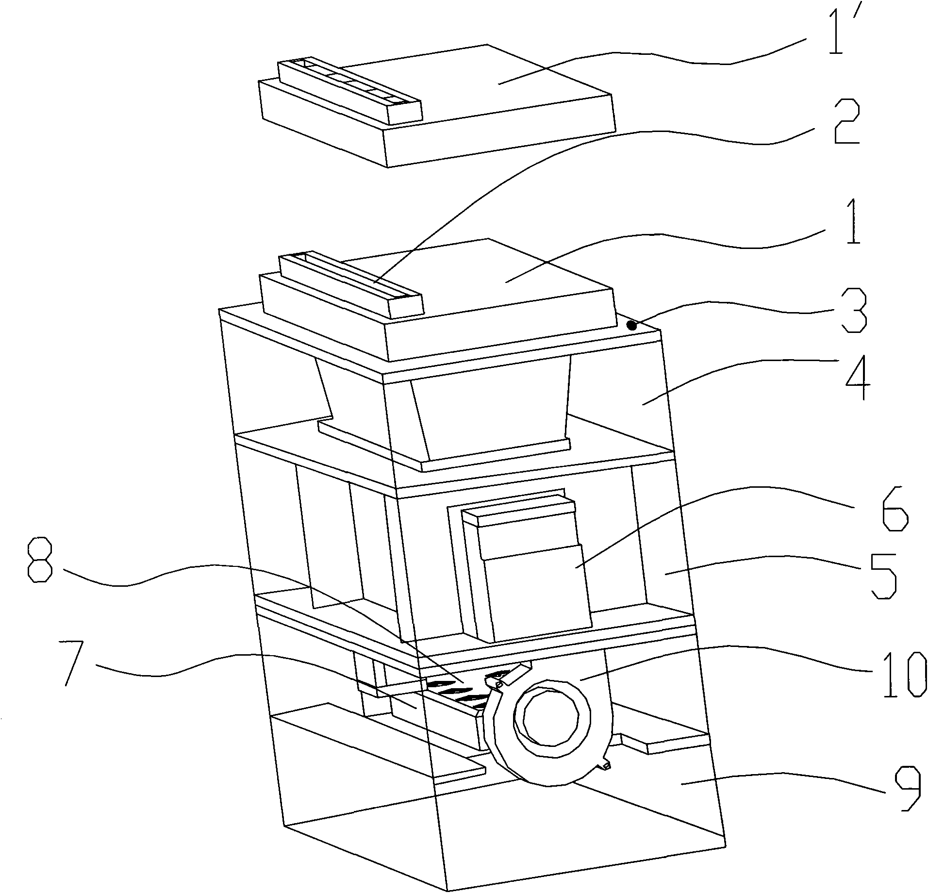
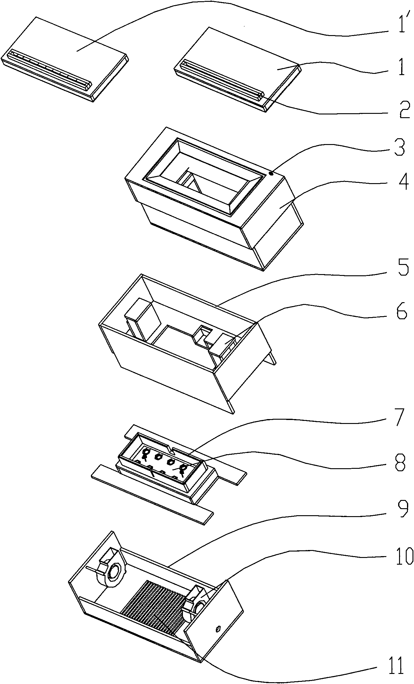
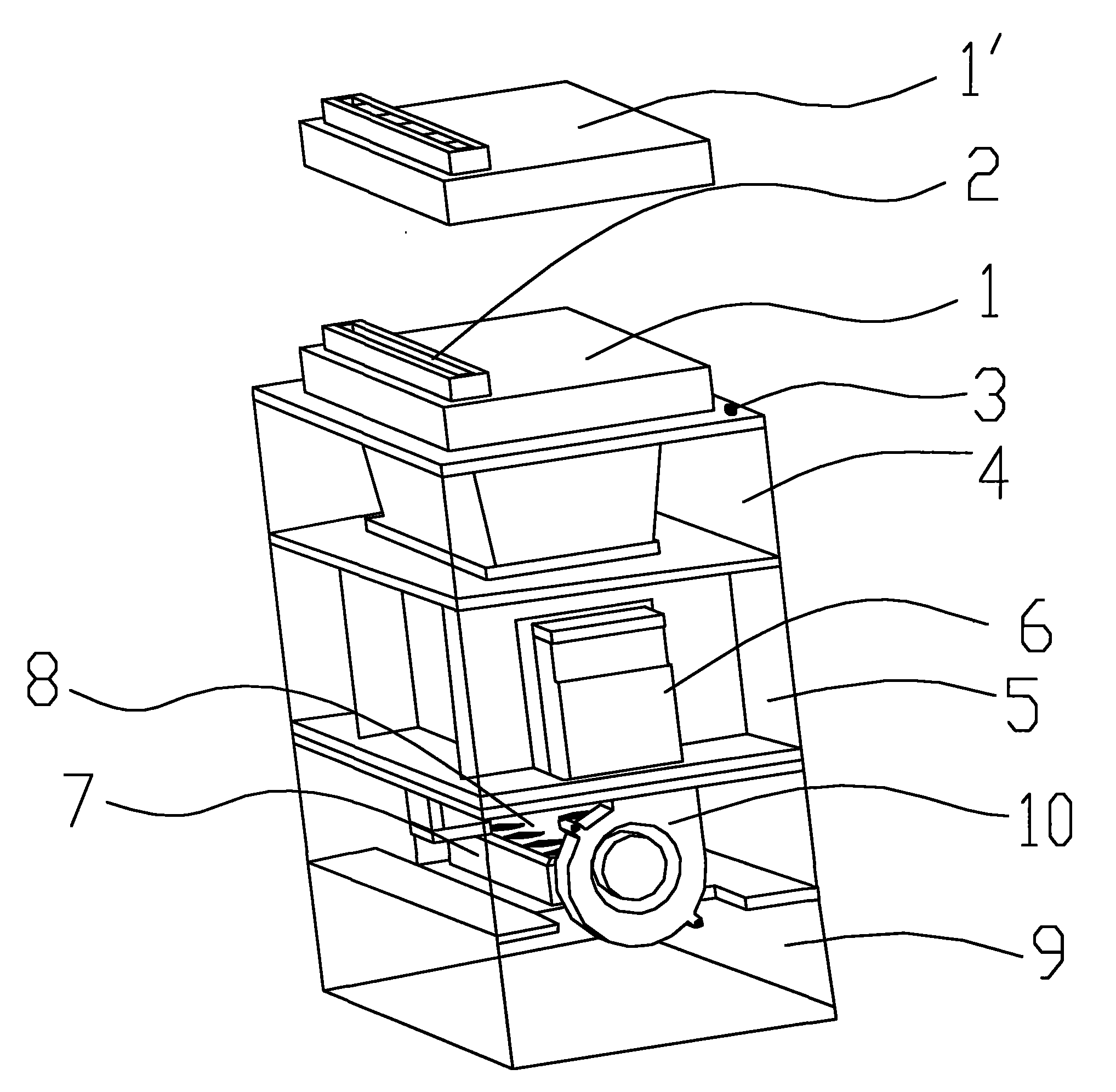
[0016] An ultrasonic flux coating process, the process steps are:

[0017] In the first step, flux is injected into the flux box 7 installed in the bottom box 9 of the ultrasonic flux coating box and the bottom is equipped with a 60KHz ultrasonic atomizer 8, and the liquid level of the flux is higher than that capable of immersing the ultrasonic mist the position of the carburetor 8;

[0018] In the second step, according to the distribution position of the solder joints on the PCBA to be welded, select a suitable nozzle board 1 and install it on the top of the top box 4 coated with ultrasonic flux, and at the same time, according to the number of solder joints on the PCBA to be soldered and the nozzle board 1 The size of the nozzle 2 adjusts the input current of the 60KHz ultrasonic atomizer 8, thereby controlling the a...


PUM


Abstract

The invention discloses an ultrasonic soldering flux coating process which comprises the following process steps of: 1. injecting a soldering flux into a soldering flux box; 2. selecting a proper spraying head plate, and simultaneously regulating the input current of a high-frequency ultrasonic atomizer as required, thereby controlling the atomized quantity of the soldering flux and the concentration of the atomized soldering flux sprayed out of a spraying head; 3. when a PCBA (Printed Circuit Board Assembly) conveyed by a conveying belt is induced by a position sensor installed on an ultrasonic soldering flux coated box body, beginning the work of the high-frequency ultrasonic atomizer and a centrifugal fan, and uniformly spaying the small-granular soldering flux atomized by the high-frequency ultrasonic atomizer onto the PCBA from the spraying head of the spraying head plate at constant speed; and 4. when the PCBA leaves, stopping the work of the high-frequency ultrasonic atomizer and the centrifugal fan until the next PCBA is induced by the position sensor, and returning to the step 3. The invention also discloses an ultrasonic soldering flux coating device for realizing the process. The invention has the advantages of uniform spraying, easy control, random regulation on the size, the height and the width of sprays as required, waste reduction of the soldering flux and reduction of environmental pollution caused by soldering flux flying.

Description

technical field [0001] The invention relates to a flux coating method and device, in particular to an ultrasonic flux coating method and device utilizing ultrasonic spraying. Background technique [0002] In the wave soldering process, the traditional flux spray generally uses air pressure or electromagnetic waves to atomize the flux, and then sprays it on the PCBA through a specific moving nozzle. Using the above technology to spray flux, the particle size of the atomized flux may not be fine enough and uneven; affected by the respective movements of the PCBA and the nozzle, the flux sprayed on the PCBA cannot be uniform. This will have a huge impact on the quality of the soldering and waste a lot of flux. There is a foreign technology of using flux to atomize through an ultrasonic nozzle, and the atomization speed depends on the speed at which the flux is introduced into the nozzle. One technique utilizing ultrasonic nozzles involves the use of moderate pressure compress...

Claims


Application Information

Patent Timeline
IPC IPC(8): B05D7/24B05B17/06B05C11/10H05K3/34
Inventor 严永农
Why Eureka
Try Eureka