
Water and gas coupled valve of gas water heater

A gas water heater, water and gas linkage technology, applied in the direction of fluid heaters, valve devices, valve details, etc., can solve problems such as increased water flow resistance, water valve damage, complex structure, etc., and achieve the effect of reducing raw material costs

Inactive Publication Date: 2010-10-20
黎晚滔
View PDF8 Cites 5 Cited by
  • Summary
  • Abstract
  • Description
  • Claims
  • Application Information

AI Technical Summary

Problems solved by technology

Because the water valve shell is made of metal material, an explosion-proof water unloading mechanism must be installed in the antifreeze port, otherwise, in cold weather, the metal shell of the water valve will be cracked after the water in the water valve freezes, and the water valve will Damage and a range of safety issues
In addition, the direct diversion reduces the bending blockage. In order to adjust the large flow and small flow fluctuation range of the water valve to meet the requirements of the national standard, the water valve is usually installed on the shell between the water-air linkage device and the valve stem. The fine-tuning mechanism that controls the large flow and small flow changes of the water outlet pipeline. In this way, the diversion channel that communicates between the water valve casing and the casing of the water-air linkage device must avoid the fine-tuning mechanism and open from the bypass. This structural design increases the water flow resistance, and the structure is complex and the processing procedures are cumbersome. In addition, due to the need for anti-rust, metal materials are usually made of copper or rust-free steel, resulting in very high production costs.

Method used


Image

  • Water and gas coupled valve of gas water heater
  • Water and gas coupled valve of gas water heater
  • Water and gas coupled valve of gas water heater

Examples


specific Embodiment approach

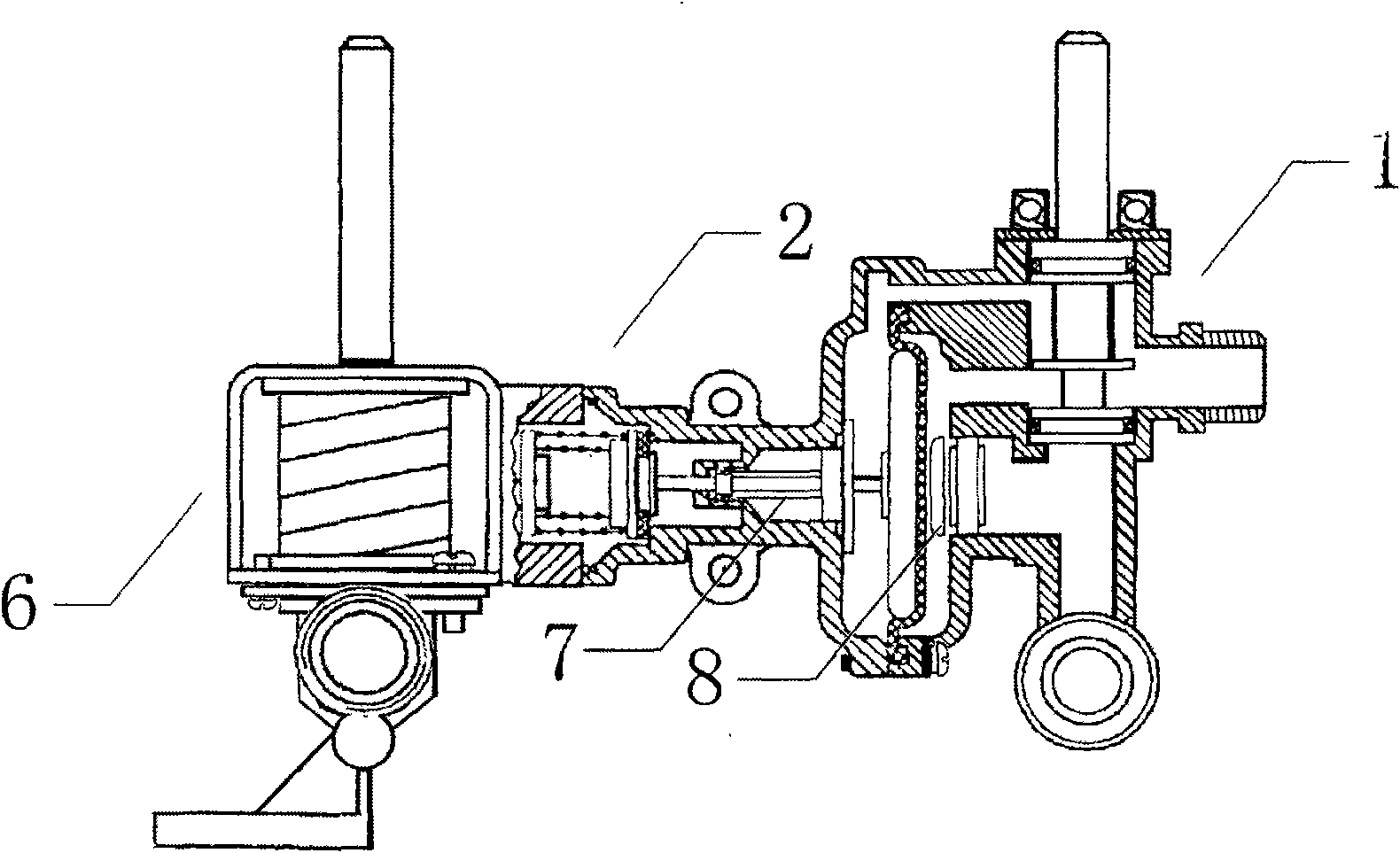
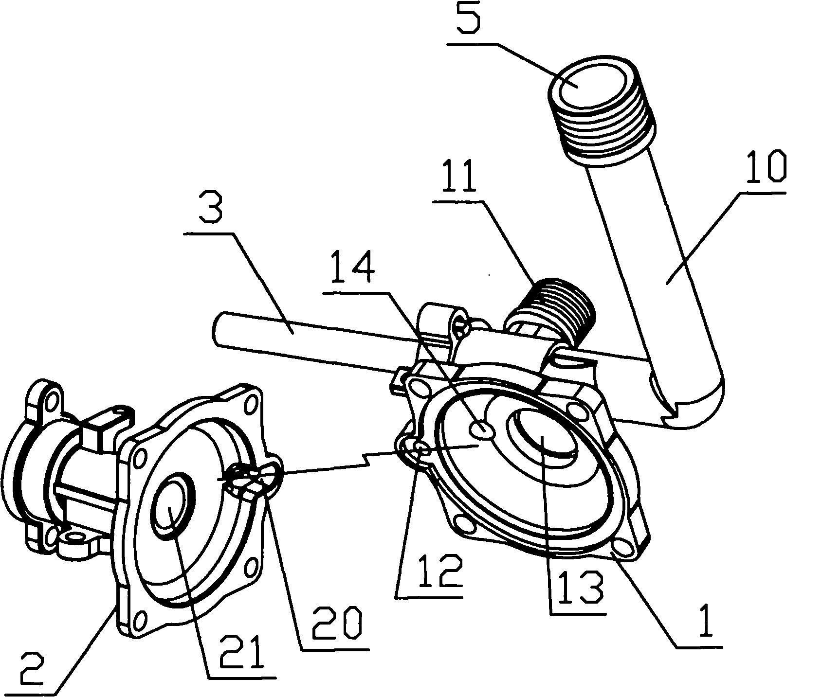
[0023] Specific implementation methods: such as Figure 1-Figure 5 As shown, the gas-fired water heater water-gas linkage valve of the present invention is mainly composed of a gas valve 6, a water valve and an intermediate water-gas linkage device, and the shell 1 of the water valve and the shell 2 of the water-gas linkage The diversion passage includes a diversion groove 12 provided on the water valve body 1 and another diversion groove 20 provided on the casing 2 of the water-air linkage device, and the two diversion grooves are arranged oppositely. They communicate with each other, and the diversion groove 12 on the water valve body 1 is in the same axial direction as the water outlet 11, which facilitates demoulding. The housing 2 center of the water-air linkage device has a through hole 21, and a linkage push rod 7 is installed on the through hole 21. In order to reduce the cost of materials and reduce the difficulty of the manufacturing process, the housing 1 of the wa...


PUM


Abstract

The invention belongs to the technical field of gas water heaters and particularly relates to a water and gas coupled valve of the gas water heater. The water and gas coupled valve of the gas water heater comprises a gas valve, a water valve and a middle water and gas linkage, wherein guide channels which are communicated with one another are positioned between a shell (1) of the water valve and the shell (2) of the water and gas linkage. The water and gas coupled valve of the gas water heater is characterized in that: the shell (1) of the water valve is made of plastics and has a water inlet (10), a water outlet (11) and an adjusting opening for adjusting water flow; and a valve rod (3) is arranged on the adjusting opening. The lower end of the valve rod (3) is circumferentially provided with a water flow channel (30) which has a grooved structure for adjusting the volume of water amount; the distance from a front end groove of the water flow channel (30) to a circle centre is not equal to that from a rear end groove of the water flow channel (30) to the circle centre; and the water flow channel has smooth transition from the front end to the rear end. The shell (1) of the water valve is made of a polyamide (nylon PA) PA66 material. The water and gas coupled valve which adopts the structure has simple and rational structural design and reduces production cost.

Description

technical field [0001] The invention belongs to the technical field of gas water heaters, and in particular relates to a water-gas linkage valve for a gas water heater. Background technique [0002] The current water-gas linkage valve used for gas water heaters mainly consists of an air valve, a water valve and an intermediate water-gas linkage device. There are diversion channels connected with each other between the bodies, so that the valve body will automatically balance when the water valve inlet and outlet fail, and the air valve linkage will automatically reset, preventing the water from continuing to boil when the air path is connected, and the hot water will burn the user or Burn out water heater, present water valve, adopt metal material to make usually, have water inlet, water outlet and antifreeze port and the valve stem of adjusting water flow size. Because the water valve shell is made of metal material, an explosion-proof water unloading mechanism must be ins...

Claims


Application Information

Patent Timeline
IPC IPC(8): F24H9/20F16K27/00F16K31/44
Inventor 黎晚滔
Owner 黎晚滔
Learn More