Rail-to-rail operational amplifier

An operational amplifier, rail-to-rail technology, applied in the direction of differential amplifiers, DC-coupled DC amplifiers, etc., can solve the problems of poor stability, low bandwidth, and long response time of constant transconductance operational amplifiers, and achieve simple structure and ensure normal operation , the effect of increasing the bandwidth

Inactive Publication Date: 2010-09-22
XI AN JIAOTONG UNIV
View PDF7 Cites 13 Cited by
  • Summary
  • Abstract
  • Description
  • Claims
  • Application Information

AI Technical Summary

Problems solved by technology

However, the stability of operational amplifiers that achieve constant transconductance is poor, and complex compensation circuits need to be designed to improve stability; in addition, the bandwidth of constant transconductance operational amplifiers is usually very low and the response time is long

Method used


Image

  • Rail-to-rail operational amplifier
  • Rail-to-rail operational amplifier
  • Rail-to-rail operational amplifier

Examples


Embodiment Construction

[0018] The present invention relates to a rail-to-rail operational amplifier suitable for a charge pump with wide output voltage range and high current matching, which will be further described below with examples in conjunction with the accompanying drawings, but does not constitute a limitation to the present invention. The circuit-level simulation of this example adopts the TSMC0.18um RF CMOS process, and is simulated under the ADE (Advanced Design Environment) environment by using SpectreRF of Cadence Company, and the power supply voltage of the circuit is 1.8V.

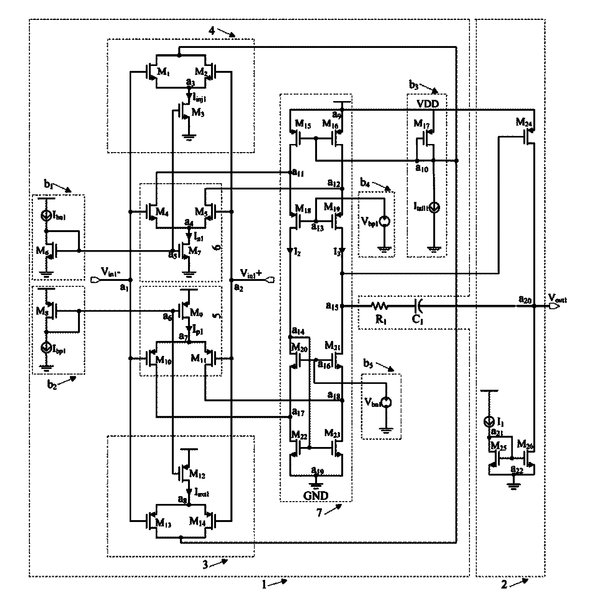
[0019] figure 1 It is a transistor-level circuit diagram of the rail-to-rail operational amplifier of the present invention. The op amp consists of three parts, namely the first stage circuit 1 of the op amp, the second stage circuit 2 and the Miller compensation circuit. The first-stage circuit 1 is the core part of the operational amplifier, which includes an N-tube input circuit 6, a P-tube input circuit 5, a...


PUM


Abstract

The invention discloses a rail-rail operational amplifier, which comprises a Miller compensation circuit respectively connected with a first-stage circuit and a second-stage circuit, wherein the first-stage circuit comprises an N-pipe input circuit, a P-pipe input circuit, a current injection circuit, a current extraction circuit, a first-stage output branch circuit and a biasing circuit, and thecurrent extraction circuit compensates the current injected into the first-stage output branch circuit by the P-pipe input circuit, so that the current in the first-stage output branch circuit is notaffected by the current in the P-pipe input circuit; similarly, the current injection circuit compensates the circuit injected into the first-stage output branch circuit by the N-pipe input circuit, so that the current in the first-stage output branch circuit is not affected by the current in the N-pipe input circuit; and the second-stage circuit is of a common-source amplifier taking a current source as a load. The operational amplifier not only has simple structure, but also ensures higher gain in a range of rail-to-rail voltage, stabilizes the DC level of the first-stage output end, and improves the bandwidth of the operational amplifier.

Description

technical field [0001] The invention belongs to the technical field of integrated circuits and relates to an operational amplifier, in particular to a rail-to-rail operational amplifier used in a unity gain buffer circuit. Background technique [0002] Rail-to-rail operational amplifiers are widely used in unity-gain buffer circuits to ensure that when the input signal voltage rail-to-rail changes, the output signal can keep up with the changes in the input signal. In audio, medical and other fields, it is necessary to use a buffer that can track the signal without distortion, which requires that the op-amp has a constant transconductance when the input signal changes from rail to rail. However, the stability of operational amplifiers that achieve constant transconductance is poor, and complex compensation circuits need to be designed to improve stability; in addition, the bandwidth of constant transconductance operational amplifiers is usually very low and the response time...

Claims


Application Information

Patent Timeline
Patent Type & Authority Applications(China)
IPC IPC(8): H03F3/45
Inventor 唐生东张鸿牛杨杨程军
Owner XI AN JIAOTONG UNIV
Why Eureka
Try Eureka