
Solar Photovoltaic Systems

a photovoltaic system and solar energy technology, applied in the direction of emergency protective circuit arrangement, dc-ac conversion without reversal, dc network circuit arrangement, etc., can solve the problem of system module loss

Active Publication Date: 2012-06-28
TESLA INC
View PDF7 Cites 113 Cited by
  • Summary
  • Abstract
  • Description
  • Claims
  • Application Information

AI Technical Summary

Benefits of technology

[0006]The solar photovoltaic (PV) power generation system provides resilience to failure. A plurality of solar PV panels are each connected to a power conditioning unit (inverter) so that energy generated by the array of solar photovoltaic modules can be shared amongst the inverters as and when necessary. In the event of an inverter failure (such as a short circuit or the inverter ceasing to feed energy into the grid) the remaining inverters on the system can then harvest the extra energy made available. This allows the system to capture all of the available energy from the array off solar PV panels even when one of the inverters (or even several of the inverters) on the system experience failure. Normally functioning inverters access energy generated by other solar PV modules on the system using a dc power distribution coupled to the solar PV panels and the power conditioning units. Control of the power distribution is implemented by a plurality of power conditioning controllers which each control the switching and connection of the dc distribution bus to the local solar PV panel and inverter. It will be appreciated however that in alternative embodiments a centralised controller may also be used to control all of the switches although in doing so the modularity of the system may be lost. Power distribution can be controlled in the event of a detection of a failure of one of the inverters by the power distribution controller, for example upon detection of a short circuit failure.
[0007]Preferably in the solar PV power generation system the first of the plurality of solar PV panels is coupled to a first of the plurality of power conditioning units, furthermore a first of the power conditioning units is also coupled to a first of the plurality of power distribution controllers. Connection to the dc distribution bus for the first solar PV panel is via switched connection to the dc distribution bus which is controlled by the power distribution controller. On detection of a fault in the connected inverter the first of the plurality of the power distribution controllers closes the first switch connection to couple the first solar PV panel to the dc distribution bus to distribute the power from the first solar PV panel. This allows the harnessed power generated by the first solar PV panel to be collected and used by other inverters upon connection to the dc bus. This ensures the system works as efficiently as possible and avoids wastage of any energy generated by the first solar PV panel if the inverter it is connected directly to should fail.
[0011]In some preferred embodiments the transmitting of fault data comprises broadcasting fault data from the power distribution controller to the other power distribution controllers such that they all receive this information and individually determine whether they should act upon the information received. Such actions may be dependent upon the data received and one or more of the other power distribution controllers may opt to enable receipt of spare dc power from the distribution bus to route through to their connected power conditioning unit. Alternatively the transmitting may comprise transmitting the fault data to a central controller or a gateway controller which may be configured to monitor and control one or more of the elements of the solar PV power generation system. The central controller may subsequently transmit fault data to one or more others of the plurality of power distribution controllers having received the fault data from the first power distribution controller. This central controller may accordingly determine which of the other inverters are to be used to harness the spare dc power and this may vary over time for example, or may be to optimise efficiency in the system for example. To provide such features the power distribution controllers may each comprise an RF transceiver to transmit and receive the fault data. Alternatively if the power conditioning unit includes an RF transceiver in order for it to be controlled via central controller then in alternative embodiments the power distribution controller may use the RF transceiver integrated into the power conditioning unit in order to transmit and receive data and therefore reduce the overall system costs.
[0014]The solar PV power generation system may be formed from a series of modular systems each including a fail-safe solar PV power conversion unit, each fail-safe solar PV power conversion unit comprising a power conditioning unit, a power distribution controller and a dc power distribution bus that can be interconnected to the dc distribution bus in other modules. Each module may then be connected to a solar PV panel. By providing fault detection within the module each module is able to protect a fault occurring within its own power conditioning unit and safely deactivate the power conditioning unit or disconnect it such that it does not impact on the rest of the system.
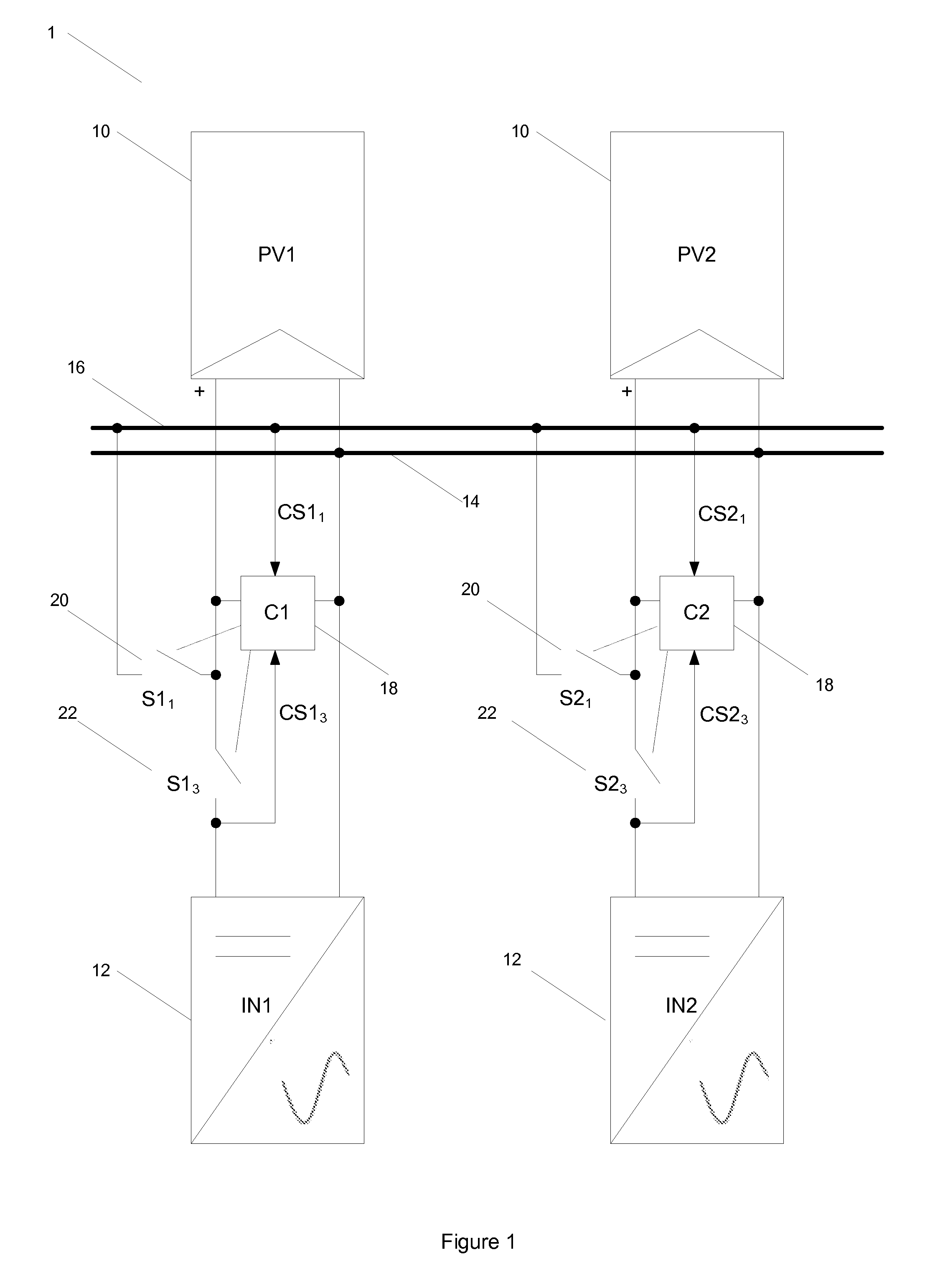
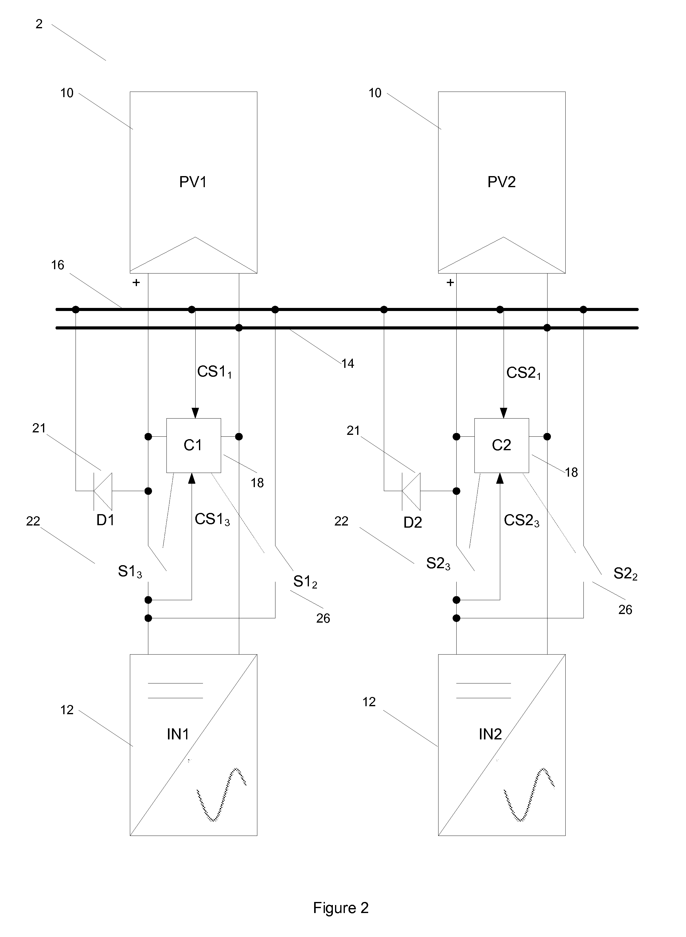
[0017]In this arrangement each of the solar PV panels is connected to a power conditioning unit and a power distribution controller is connected between the solar PV panels and power conditioning units to sense / detect a failure in the power conditioning unit. A first power distribution bus (PDB) switch provides connection from between the first solar PV panel and first power conditioning unit through to the power distribution bus so that on a failure being detected in the first power conditioning unit power may be distributed to the dc distribution bus. Similarly the second solar PV panel and second power conditioning unit are coupled by a second PDB switch connected between the second solar PV panel and second power conditioning unit which also connects to the dc distribution bus. When the first power conditioning unit has failed the second PDB switch may be closed to receive power routed to the power distribution bus via the first PDB switch to the second power conditioning unit via this second PDB switch. The PCU switches provide short circuit protection, enabling the respectively connected power conditioning units to be detected from the system in the presence of a short circuit.
[0018]The fault detector in one or both of the power distribution controllers (or separate to the power distribution controllers but still part of the system) may be a short circuit detector for example to detect a short between the dc rail inputs to the power conditioning unit. On detecting a short the corresponding power conditioning unit switch may be opened to prevent the short impacting remaining components of the system.

Problems solved by technology

It will be appreciated however that in alternative embodiments a centralised controller may also be used to control all of the switches although in doing so the modularity of the system may be lost.

Method used


Image

  • Solar Photovoltaic Systems
  • Solar Photovoltaic Systems
  • Solar Photovoltaic Systems

Examples


Embodiment Construction

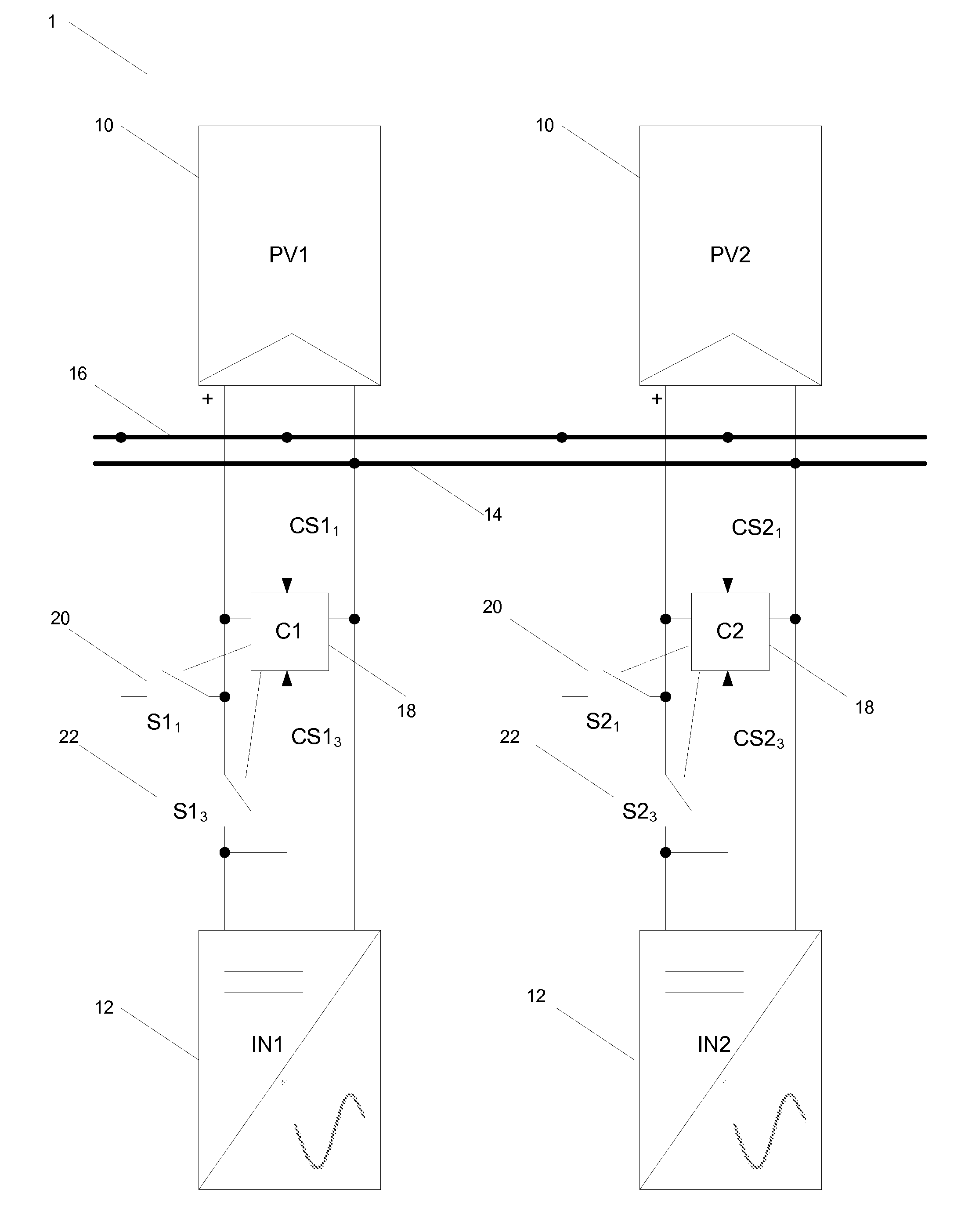
[0026]The embodiments show a solar photovoltaic module array connected to inverters, with the inverters being connected to the grid (mains electric grid). A number of connection schemes between inverters and solar modules on the array are possible, two of which are presented in the embodiments in FIGS. 1 and 2.

[0027]Referring to FIG. 1, this shows an embodiment of the solar PV power generation system comprising solar PV panels 10 (PV1, PV2) and power conditioning units 12 (IN1, IN2). Further solar PV panels and power conditioning units may also be added and connected in the same manner as PV1 and PV2. Each solar PV panel (PV1, PV2) is coupled to a respective power conditioning unit (IN1, IN2) to transmit dc power from the solar PV panels to the respective power conditioning unit for conversion to an ac mains output. A power distribution controller 18 (C1, C2) is coupled between each solar PV panel and power conditioning unit pair and controls the opening and closing of switches conn...


PUM


Abstract

Improved techniques for photovoltaic power generation are described. Inverter failure is can be a significant problem in solar photovoltaic systems as it can lead to loss of opportunity to harvest energy. A solar photovoltaic (PV) power generation system is described comprising solar PV panels and power conditioning units. A dc power distribution bus is coupled to the solar PV panels and the power conditioning units to switchably share dc power from the solar PV panels between the power conditioning units. Power distribution controllers detect a faulty power conditioning unit and reroute power from a solar PV panel coupled to the faulty power conditioning unit to other power conditioning units via the dc distribution bus.

Description

FIELD OF THE INVENTION[0001]This invention relates to improved techniques for photovoltaic power generation.BACKGROUND TO THE INVENTION[0002]Inverter failure is can be a significant problem in solar photovoltaic systems as it can lead to loss of opportunity to harvest energy. The problem is even more pronounced in central and string inverter systems where failure of the inverter can end the opportunity to harvest energy for the entire system. The problem of failure in micro-inverter systems is less severe because energy harvest is localised. However, even in such systems the energy loss due to failure to harvest, in failed parts of the system, may be significant depending on down time, size of system and number of failures.[0003]There is therefore a need to address this problem to provide solar photovoltaic systems resilient to inverter failure.[0004]Background prior art can be found in: WO2010 / 062410A1; WO2005 / 076444A1 and WO2004 / 001942A1.SUMMARY OF THE INVENTION[0005]According to ...

Claims


Application Information

Patent Timeline
IPC IPC(8): H02J1/00H02M7/537
CPCY02E10/563H02J3/383H02J2300/24H02J3/381Y02E10/56H02J3/48H02H7/122H02M7/44
Inventor MUMTAZ, ASIMENGLE, JR., PAUL RANDALAMARATUNGA, GEHAN ANIL JOSEPHMATTHEW, ANDREW JOHN
Owner TESLA INC
Learn More