
Liquid heater with low power consumption, control method and manufacturing method thereof

A heating device and power consumption technology, applied in the field of liquid heating devices of automatic drinking fountains or beverage diverters, can solve the problems of easy formation of cracks, high heating temperature, large heating unit, etc., and achieve the promotion of liquid heating and high heat transfer. coefficient, the effect of fast heating

Inactive Publication Date: 2010-09-22
TOPMASTER IN TECH
View PDF5 Cites 1 Cited by
  • Summary
  • Abstract
  • Description
  • Claims
  • Application Information

AI Technical Summary

Problems solved by technology

When this happens, due to the difference in heat, each part of the heating unit will bear a huge and uneven heat pressure, and cracks will easily form after long-term use
When cracks are formed in the heating unit, the heating components of the unit will inevitably be affected and even easily destroyed
In addition, the circuit is usually located on the other side of the heating unit, and a crack in the heating unit will also destroy the heating resistor circuit
Likewise, with common liquid heaters, when no or insufficient water is sourced from the heating element, the heating element can easily overheat and be destroyed
To solve this problem, some common hot water supply devices usually have a complex electronic temperature control to monitor and limit the maximum heating temperature
However, these circuits often do not solve the problem properly and often create other new problems
Among other things, these circuits are very expensive and need to be added to the production cost

Method used


Image

  • Liquid heater with low power consumption, control method and manufacturing method thereof
  • Liquid heater with low power consumption, control method and manufacturing method thereof
  • Liquid heater with low power consumption, control method and manufacturing method thereof

Examples


Embodiment 1

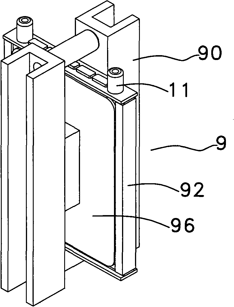
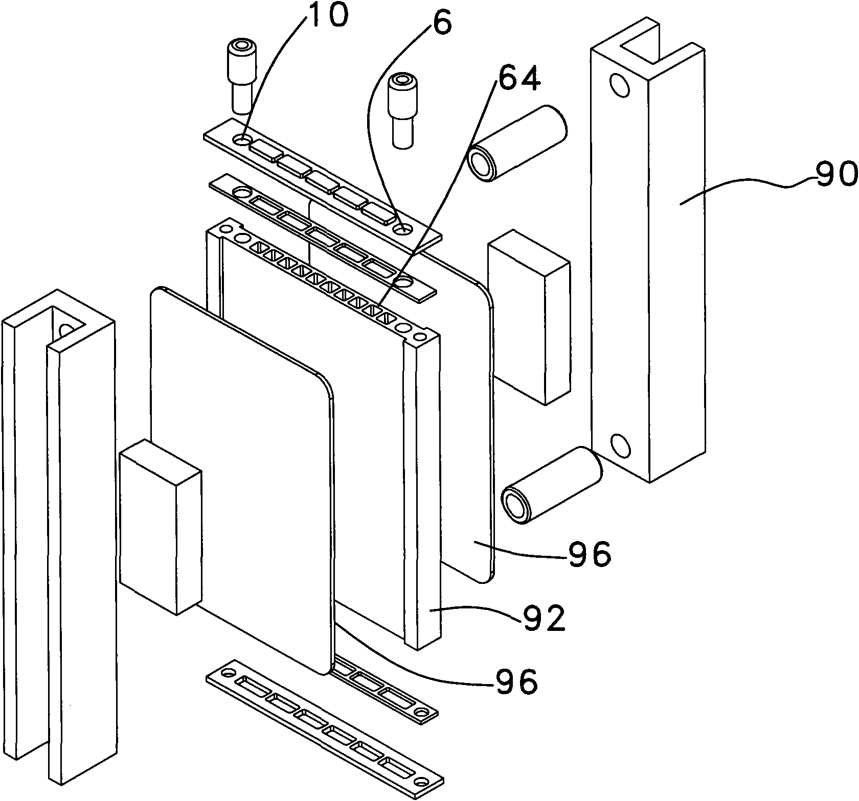
[0056] attached Figure 1 to Figure 2 It is a specific embodiment of the core assembly 9 in a liquid heating device (such as a drinking water heating device). The core 92 shown in this embodiment is integrally manufactured with the heat diffusion components 64 on both sides and the channel. The core 92 is actually extruded from aluminum, such as aluminum alloy, and the two ends are connected by cover plates to form the core as a whole, as shown in the attached figure 1 And attached figure 2 shown. After the core 92 is formed, two heat-generating components 96 are disposed opposite to the two surfaces of the core 92 and sandwich the core. After the two heating components 96 have been configured, the two bracket components 90 and the corresponding pressing blocks are relatively arranged on the other surface of the heating component 96. The bracket component 90 provides a pressure perpendicular to the core assembly 9 to make the heating component 96 is attached to the core 9...

Embodiment 2

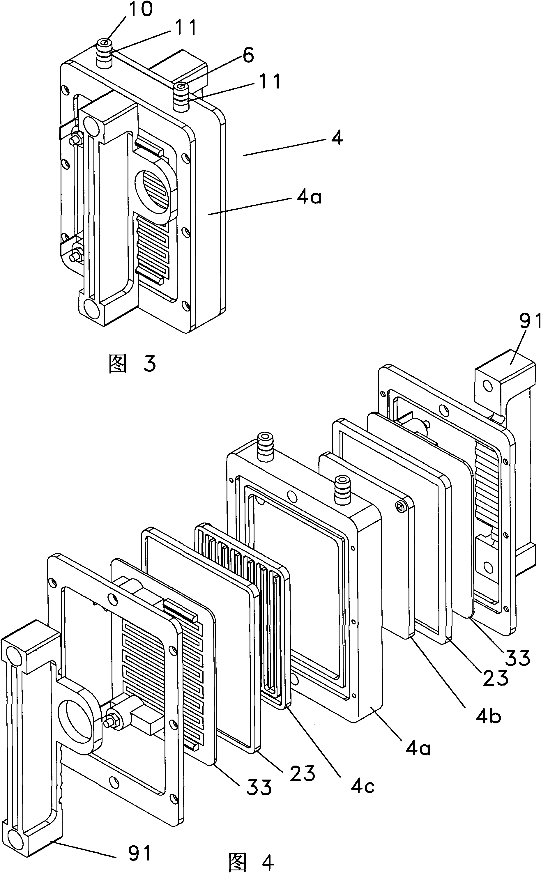
[0060] attached image 3 to attach Figure 4 Shown is another specific embodiment of a core assembly within a liquid heating apparatus. as attached image 3 As shown, the liquid heating device inner core assembly is generally indicated at 4 . The inner core assembly 4 of the liquid heating device is provided with an inlet 6 , an outlet 10 and two joints 11 .

[0061] attached Figure 4 to attach image 3 An exploded view of the core assembly inside a medium liquid heating device. The liquid heating core assembly 4 includes a core base assembly 4a in the middle of the assembly. Two sides of the core base assembly 4a respectively provide a space for accommodating the channel 4b and the channel 4c.

[0062] In this embodiment, the core assembly 4 is different from the embodiment 1. The core assembly of embodiment 1 is manufactured by integrating the channel and the thermal diffusion part. However, in Embodiment 2, the core assembly 4 is respectively configured as a core ...

Embodiment 3

[0065] attached Figure 5 to attach Figure 6 Shown is another embodiment of a core assembly within a liquid heating apparatus. as attached Figure 5 The liquid heating unit inner core assembly is generally indicated at 2 as shown. Two joints 11 are attached to the top of the core part 2a in this liquid heating device.

[0066] Figure 6 It is an exploded view of each main part of the core components in the liquid heating device. The core assembly 2 of the liquid heating device comprises a core part 2 a in the middle part of the device 2 . The core part 2a provides a liquid inlet level 6 through which liquid is introduced into the core part 2a. The core part 2a also provides a liquid outlet level 10 through which the heated liquid leaves the core part 2a. A thermal diffusion component 24 covers the core component 2 a to form a channel, a heating element 32 is attached to the other surface of the thermal diffusion component 24 , a pressure ring 36 and a base 38 form a pr...


PUM


Abstract

The present invention provides a liquid heater with low power consumption, a control method and a manufacturing method thereof. The liquid heater comprises a core assembly for heating the liquid. The core assembly is provided with a water inlet position, a water outlet position and a channel. The channel is used for connecting between the water inlet position and the water outlet position. The core assembly is provided with a heating assembly. The heating assembly comprises a resistor unit which uses ohm as a unit. The resistance is smaller than 31 and larger than 10. The electric power of the heating assembly uses watt as a unit and is determined according to a voltage supplied by an electrical network. The ratio between the electric power of the heating assembly and the surface area of the heating assembly is smaller than 33 and larger than 14. The core assembly is internally provided with a heat diffusion component. The heat diffusion component is a planar component. Furthermore one surface of the heat diffusion component directly contacts the channel, and the other surface clings to the heating assembly. A heating controller of the heating assembly is controlled through duty ratio. The duty ratio is the ratio accounted by the time of activating the heating assembly with a period of one second according to different liquid input temperature.

Description

technical field [0001] The present invention relates to a liquid heating device with low power consumption, a control method and a manufacturing method of the device, especially a liquid heating device for an automatic water dispenser or a beverage diverter, such as some well-known coffee machines or Water heaters and other devices. technical background [0002] There are different liquid heating devices on the market, such as hot water or beverage diverters. Each liquid heating device has different designs to meet the needs of different users. For example, one of the basic needs is a commercial drinking water heater for hotels. This application requires that a large amount of hot water can be provided to multiple hotel rooms at the same time without hindrance. Based on this demand, the liquid heater in the hotel is usually equipped with a water storage tank to store and maintain a relatively large amount of hot water to meet the consumption of hotel guests, so supplying h...

Claims


Application Information

Patent Timeline
Patent Type & Authority Applications(China)
IPC IPC(8): F24H1/00F24H9/18F24H9/20
Inventor 陈永辉陈永坚
Owner TOPMASTER IN TECH
Learn More