
Absorption control method of ammonia inside SCR (Silicon Controlled Rectifier) catalyst

A SCR catalytic converter, adsorption control technology, applied in chemical instruments and methods, separation methods, electronic control of exhaust gas treatment devices, etc., can solve the problem of not considering the control measures of ammonia gas storage and the amount of ammonia gas escaped from catalytic converters , Inaccurate calculation results of ammonia gas accumulation, etc., to achieve the effects of curbing ammonia gas leakage, eliminating response lag, simplifying calculation content and SCR system structure

Active Publication Date: 2010-09-15
DONGFENG MOTOR CORP HUBEI
View PDF4 Cites 19 Cited by
  • Summary
  • Abstract
  • Description
  • Claims
  • Application Information

AI Technical Summary

Problems solved by technology

[0008] (1) In the calculation of the accumulated amount of ammonia gas, the escape amount of ammonia gas at the outlet of the catalytic converter is not considered, and the calculation result of the accumulated amount of ammonia gas is inaccurate;
[0009] (2) The control measures under the condition that the amount of ammonia storage is far less than the set value are not considered;
[0010] (3) Restricted by factors such as asynchronous sensor signal response, poor reliability, low precision and high cost, this technology is difficult to put into practical use

Method used

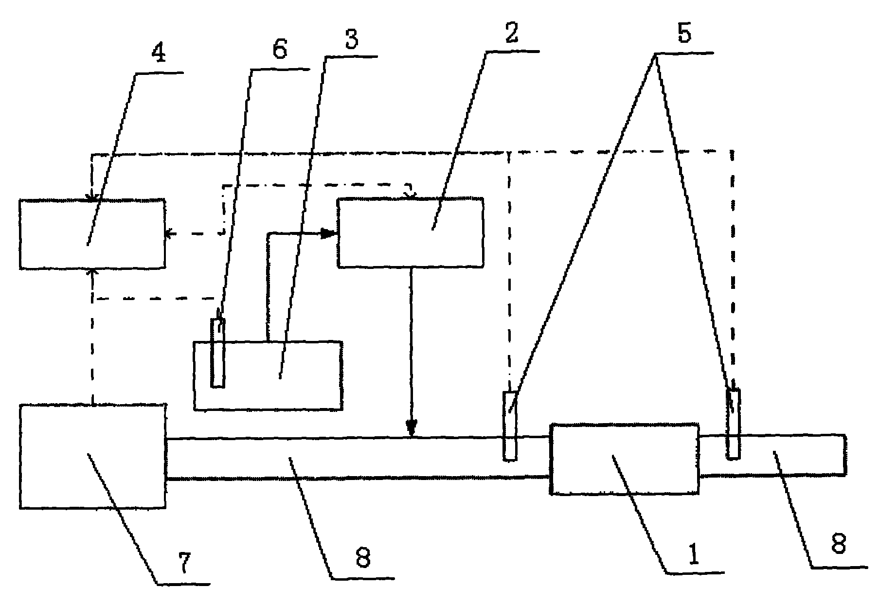
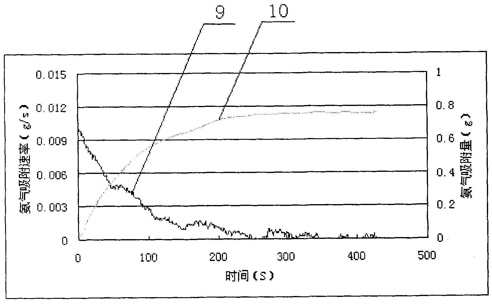
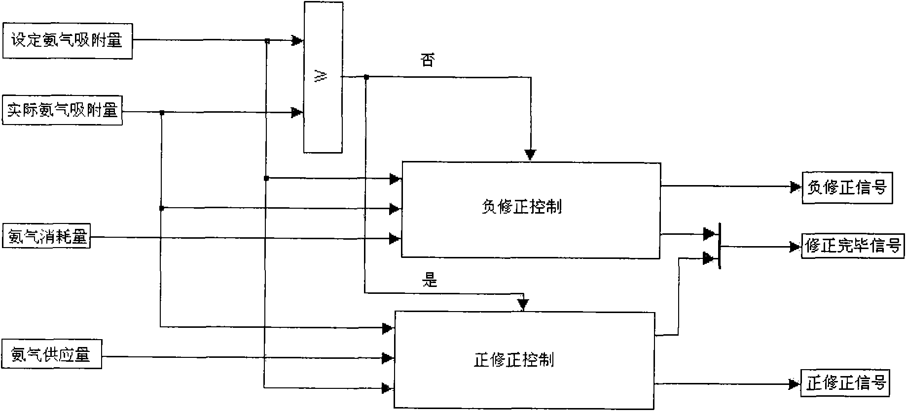

Image

  • Absorption control method of ammonia inside SCR (Silicon Controlled Rectifier) catalyst
  • Absorption control method of ammonia inside SCR (Silicon Controlled Rectifier) catalyst
  • Absorption control method of ammonia inside SCR (Silicon Controlled Rectifier) catalyst

Examples


Embodiment 1

[0055] After the engine starts, after a period of time, it enters the temperature range 1, and the background ammonia adsorption amount is 0. Set the ammonia adsorption amount as the saturated ammonia adsorption amount at the current temperature.

[0056] The engine has been running for 30 seconds in temperature range 1, and the continuous injection time of urea is 20 seconds, then the saturated ammonia adsorption amount Q in the current temperature range is 1max = 0.201g.

[0057] After the engine runs in temperature range 1 for 30 seconds, it enters into temperature range 2, then background ammonia adsorption amount = ammonia adsorption amount in the previous temperature range = 0.201g. And the current saturated ammonia adsorption amount = Q 2max = 0.184g.

[0058] Therefore, at the moment of entering the temperature range 2, the actual adsorption amount of ammonia gas by the catalytic converter = background ammonia adsorption amount = 0.201 g.

[0059] Since the actual ...

Embodiment 2

[0061] After the engine has been running in temperature range 2 for a period of time, the negative correction has ended and it enters temperature range 1, then the background ammonia adsorption amount is Q 2max That is 0.184g. The set ammonia adsorption amount is still the saturated ammonia adsorption amount at the current temperature.

[0062] Therefore, at the moment of entering the temperature range 2, the actual adsorption amount of ammonia gas by the catalyst = the background ammonia adsorption amount = 0.184g. Since the actual adsorption amount of 0.184g of ammonia by the catalytic converter is less than the current saturated ammonia adsorption amount of 0.201g, the positive correction control is activated. The increased ammonia adsorption was calculated from the increased flow rate of urea. Then add the actual adsorption amount of ammonia gas of 0.184g to the increased amount of ammonia gas adsorption to obtain a new actual adsorption amount of ammonia gas, and compar...

Embodiment 3

[0064] Set the ammonia adsorption amount to 70% of the saturated adsorption amount at the current temperature.

[0065] The engine has been running for 20 seconds in the temperature range 1, and the continuous injection time of urea = 5 seconds, then according to the adsorption function f 1 (t), the ammonia adsorption amount=0.08g in the current temperature range;

[0066] After the engine runs in temperature range 1 for 20 seconds and enters temperature range 2, then background ammonia adsorption amount = ammonia adsorption amount in the previous temperature range = 0.08g;

[0067] Ammonia saturated adsorption capacity in the current temperature range = Q 2max =0.184g; Set ammonia adsorption capacity=0.184×70%=0.118g;

[0068] At the moment of entering the temperature range 2, the actual ammonia adsorption amount of the catalyst = the background ammonia adsorption amount = 0.08g;

[0069] Since the actual adsorption amount of ammonia gas


PUM


Abstract

The invention provides an absorption control method of ammonia inside an SCR (Silicon Controlled Rectifier) catalyst, comprising the following steps of: measuring temperature inside the SCR catalyst, actual ammonia adsorption quantity and saturated ammonia adsorption quantity at the current temperature; comparing the magnitude of the actual ammonia adsorption quantity and set ammonia adsorption quantity; if the actual ammonia adsorption quantity is more than the set ammonia adsorption quantity, increasing ammonia consumption quantity till the actual ammonia adsorption quantity is equal to the set ammonia adsorption quantity; and if the actual ammonia adsorption quantity is not more than the set ammonia adsorption quantity, increasing ammonia supplying quantity till the actual ammonia adsorption quantity is equal to the set ammonia adsorption quantity. The invention considers two conditions that the actual ammonia adsorption quantity is more than or less than the set ammonia adsorption quantity, also obtains an empirical formula of ammonia adsorption rate, approximates temperature intervals with same ammonia adsorption rate, fits an absorption function and computes the ammonia adsorption quantity through the absorption function, thereby accurately and reliably estimating the ammonia adsorption quantity; and in addition, the invention simplifies the operation content and the structure of an SCR system, enhances the stability of the SCR system, reduces the cost of the SCR system and can be actually applied.

Description

technical field [0001] The invention relates to the technical field of selective catalytic reduction (SCR) in aftertreatment of exhaust gas of diesel engines, in particular to an ammonia adsorption control method in an SCR catalytic converter. technical background [0002] Diesel engine exhaust contains harmful substances nitrogen oxides (referred to as NO X ), whose main components are NO and NO 2 . Diesel engine emission regulations for NO X Emissions to the atmosphere are limited. SCR technology is diesel engine NO X The main control technology for emissions. This technology utilizes the decomposition of urea aqueous solution to generate ammonia gas, and under the catalytic action of SCR catalyst, ammonia gas and NO X A selective catalytic reduction reaction occurs, nitrogen and water are generated and discharged into the atmosphere, and urea aqueous solution is sprayed into the exhaust of the diesel engine to control NO X emissions to the atmosphere. The followin...

Claims


Application Information

Patent Timeline
IPC IPC(8): F01N3/20F01N9/00B01D53/94
CPCY02T10/24Y02T10/47Y02T10/12Y02T10/40
Inventor 刘丙善李志明殷勇阳松林
Owner DONGFENG MOTOR CORP HUBEI
Learn More