Resource recycling method of metallurgical flue gas

A technology of recycling and flue gas, which is applied in the field of energy chemistry, can solve the problem of insufficient use of heat and achieve the effect of reducing emissions

Inactive Publication Date: 2012-03-21
KUNMING UNIV OF SCI & TECH
View PDF0 Cites 0 Cited by
  • Summary
  • Abstract
  • Description
  • Claims
  • Application Information

AI Technical Summary

Problems solved by technology

In particular, the heat in the high-temperature flue gas produced in the pyrometallurgical process has not been fully utilized

Method used


Image

  • Resource recycling method of metallurgical flue gas
  • Resource recycling method of metallurgical flue gas
  • Resource recycling method of metallurgical flue gas

Examples


specific Embodiment approach

[0019] DETAILED DESCRIPTION OF THE PREFERRED EMBODIMENTS The essence of the present invention will be further described with examples in conjunction with the accompanying drawings, but each example does not constitute a limitation to the present invention.

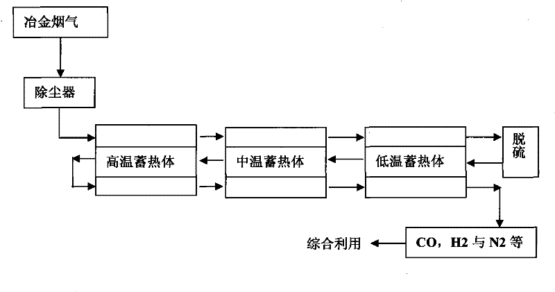
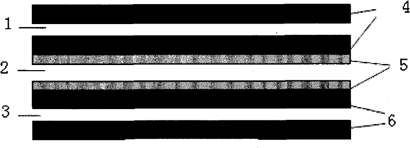
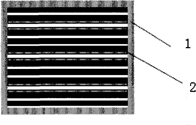
[0020] The specific implementation process is as follows: figure 1 with figure 2 First, the high-temperature metallurgical flue gas directly coming out of the metallurgical furnace passes through the "regenerator layer" of the cascaded regenerator after dedusting, followed by high-temperature regenerator (about 850°C)-medium-temperature regenerator (about 550°C)-low temperature Regenerator (about 250°C); the flue gas that has undergone heat exchange from the low-temperature regenerator passes through the desulfurization purification device to fully remove the acid gas in the flue gas; the flue gas after desulfurization is reversed to the deployment gas Through the catalytic "heat exchange layer" of the cascaded regenerat...

Embodiment 1

[0023] Flue gas composition of a copper smelter

[0024]

[0025] Catalytic material: Ni / Al 2 o 3

[0026] High temperature heat storage body: working temperature, 860°C; phase change heat storage material, Ni / Na 2 CO 3

[0027] Medium temperature heat storage body temperature: working temperature, 572°C; phase change heat storage material, Al / Al 2 o 3

[0028] Low temperature heat storage body temperature: working temperature, 265°C; phase change heat storage material, KCl+ZnCl 2

[0029] Outlet flue gas temperature: 260°C

[0030] Deployment gas: CH 4

[0031] CH 4 with CO 2 Conversion rate: 96%, 86%

[0032] Export flue gas composition

[0033]

Embodiment 2

[0035] Composition of flue gas during blast furnace smelting in a steel plant

[0036]

[0037] Catalytic material: Ni / Al 2 o 3

[0038] High temperature heat storage body: working temperature, 880°C; phase change heat storage material, Ni / Na 2 CO 3

[0039] Medium temperature heat storage body temperature: working temperature, 562°C; phase change heat storage material, Al / Al 2 o 3

[0040]Low temperature heat storage body temperature: working temperature, 245°C; phase change heat storage material, KCl+ZnCl 2

[0041] Deployment gas: CH 4 , O 2

[0042] CH 4 with CO 2 Conversion rates: 95%, 84%

[0043] Export flue gas composition

[0044]


PUM


Abstract

The invention discloses a resource recycling method of metallurgical flue gas, comprising the following steps: dust-removed flue gas coming out of a metallurgical furnace passes through heat storage layers of stair heat storage bodies in the order from a high-temperature heat storage body, to a medium-temperature heat storage body and to a low-temperature heat storage body; the heat-exchanged flue gas coming out of the low-temperature heat storage passes through a desulfurizing and purifying device; the desulfurized flue gas and blending gas reversely pass through the catalytic heat-exchange layers of the stair heat storage bodies in the order from the low-temperature heat storage body, to the medium-temperature heat storage body and to the high-temperature heat storage body; raw material gas in the catalytic layers of the heat storage bodies is reformed three times to obtain synthesis gas; and the synthesis gas coming out of the catalytic layer of the high-temperature heat storage body passes through another heat storage layer in the heat storage bodies in the order from the high-temperature heat storage body to the medium-temperature heat storage body and to the low-temperature heat storage body to achieve heat recovery; and finally the flue gas is discharged from the low-temperature heat storage body for next procedure. The invention fully utilizes resources in the metallurgical flue gas, greatly reduces the discharge of CO2 and solves the problem of high-temperature desulfurization.

Description

technical field [0001] The invention relates to a comprehensive utilization technology of metallurgical flue gas, which is a kind of CO 2 A new technology for emission reduction and resource utilization of industrial flue gas belongs to the field of energy chemistry. technical background [0002] The rising temperature of the earth's surface, rising sea level, and frequent occurrence of extreme and severe weather have aroused the attention of all mankind on the "greenhouse effect". CO 2 It is the main greenhouse gas that causes the greenhouse effect and has been regarded as the third generation of air pollutants. With the continuous advancement of the world's industrialization process, carbon-containing fossil energy, mainly oil, coal, and natural gas, is widely used in human production and living activities, breaking the original carbon balance of the natural biosphere and atmosphere. In order to realize the sustainable development of human society, with the "Kyoto Protoc...

Claims


Application Information

Patent Timeline
Patent Type & Authority Patents(China)
IPC IPC(8): C01B3/38B01D53/86
CPCY02P20/10Y02P20/129
Inventor 李孔斋王华祝星魏永刚胡建杭
Owner KUNMING UNIV OF SCI & TECH
Why Eureka
Try Eureka