
Rotating and twisting device of optical fiber image inverter

A technology of image inverter and braking device, which is applied in the direction of bundle of optical fibers, etc., can solve the problems of difficult product quality assurance, uneven heating of composite wire rods, and falling deviation, so as to avoid uneven heating, easy to operate, and easy to manufacture. low cost effect

Active Publication Date: 2011-09-28
GUANGZHOU HONSUN OPTOELECTRONICS
View PDF0 Cites 2 Cited by
  • Summary
  • Abstract
  • Description
  • Claims
  • Application Information

AI Technical Summary

Problems solved by technology

In this way, the composite wire rod has to stop rotating during the long-term high-temperature process from the beginning of twisting to the end of twisting, and the composite wire rod will be heated at rest. Uneven heating of the composite wire rod and the phenomenon of "falling and offset" may still occur, and the product quality is difficult to guarantee.

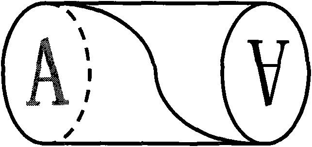
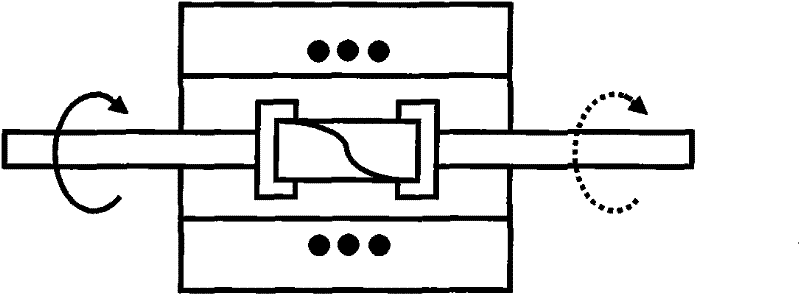
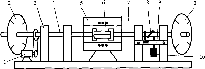
Method used


Image

  • Rotating and twisting device of optical fiber image inverter
  • Rotating and twisting device of optical fiber image inverter
  • Rotating and twisting device of optical fiber image inverter

Examples


Embodiment Construction

[0013] The present invention will be further described below in conjunction with the accompanying drawings.

[0014] according to figure 1 The principle of the optical fiber inverter is shown. In order to make the optical fiber inverter, firstly, thousands of optical fiber multifilaments are regularly arranged, melted and pressed into an optical fiber composite wire rod, and then placed on a special device for heating and twisting. Specific device reference image 3 Assembled with the above summary of the invention, wherein the bracket 9 of the braking device is fixed on the double columns of the frame 3, and the motor 1 drives the main shaft 4 to rotate through the belt. Such as figure 2 , image 3 , clamp a Φ20mm×30mm optical fiber composite wire rod 6 between the main shaft 4 and the driven shaft 7 in a horizontal state, then place it in the heating furnace 5, and adjust and record the corresponding starting points of the left and right angle discs 2 scale.

[0015] S...


PUM


Abstract

The present invention discloses a rotating and twisting device of an optical fiber image inverter which is a device with braking function, simplicity and practical utility, thus realizing rotational heating and twisting of the optical fiber composite silk rod from beginning to end, overcoming the defects of uneven heating, easy cracking and severe distortion due to falling deviation of a workpiece in an ordinary twisting method of an optical fiber image inverter, and dramatically enhancing the qualified rate of the product quality. The device has the advantages of simplicity, practical utility, low cost of manufacture and easy operation.

Description

technical field [0001] The invention relates to a manufacturing technology of an image transmission device of fiber optics, in particular to a twisting device of an optical fiber image inverter. Background technique [0002] The fiber optic image inverter is an image transmission device made of tens of millions of optical glass fibers less than or equal to 6 microns that are regularly arranged and twisted. It can rotate the input image 180° around its axis and output it, thus becoming an inverted image. like. It is one of the core components of photoelectric instruments, especially the new generation of low-light image intensifiers, and is widely used in medical, night vision and other fields. [0003] The manufacturing method of the optical fiber inverter is generally firstly arrange the optical fibers regularly, melt and press them into an optical fiber composite wire rod, and then heat and twist it on a special device. After twisting, one end of each optical fiber in th...

Claims


Application Information

Patent Timeline
Patent Type & Authority Patents(China)
IPC IPC(8): G02B6/04
Inventor 何相平郭清邱晓娇钟汉民王斌
Owner GUANGZHOU HONSUN OPTOELECTRONICS
Learn More