Vacuum cavity isolating mechanism

A technology of vacuum cavity and isolation mechanism, which is applied in the direction of vacuum evaporation plating, electric solid devices, semiconductor devices, etc. It can solve problems such as unstable performance, large stress, and unclean components, and achieve firm and reliable connection, high performance Stable, Pure Effects

Inactive Publication Date: 2010-08-25
DONGGUAN ANWELL DIGITAL MASCH CO LTD
View PDF0 Cites 7 Cited by
  • Summary
  • Abstract
  • Description
  • Claims
  • Application Information

AI Technical Summary

Problems solved by technology

These impurities and unstable gas diffusion will cause defects such as uneven film thickness, unclean composition, unstable performance, high stress, and weak adhesion, which will affect the quality of the coating film, and the quality of the film will directly affect the luminous efficiency of the display device.
[0004] The general coating equipment does not take corresponding protective measures between the evaporation source and the processing plate in the vacuum chamber, and this kind of coating equipment can no longer meet the needs of the production process.
Although there have been some isolation mechanisms that isolate impurities by setting baffles between the evaporation source and the processing plate to control the opening and closing of the baffles to solve the above problems, these baffles and the mechanism for controlling the baffles will all be set In the vacuum chamber, these baffle control mechanisms inside the chamber are likely to cause problems such as vacuum pollution and performance aging of the control mechanism. There are also other baffle control mechanisms installed outside the vacuum chamber, such as handwheels, motor drives, etc. , but the above-mentioned structures all have the disadvantages of low degree of automation, complex structure and high production cost.

Method used


Image

  • Vacuum cavity isolating mechanism
  • Vacuum cavity isolating mechanism
  • Vacuum cavity isolating mechanism

Examples


Embodiment Construction

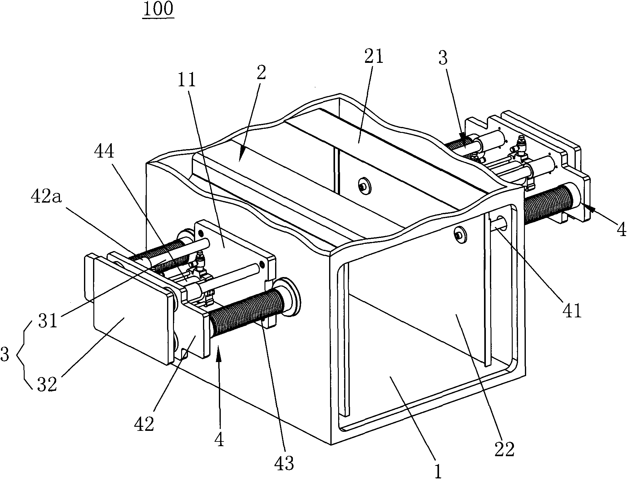
[0022] As shown in Figure 1 is the first embodiment of the present invention, as shown in the figure, the vacuum chamber isolation mechanism 100 includes a vacuum chamber 1, two blocking covers 2, two guiding mechanisms 3 and two control mechanisms 4, two blocking covers 2. The two guide mechanisms 3 and the two control mechanisms 4 are respectively arranged on both sides of the vacuum chamber 1, the vacuum chamber 1 is a hollow and sealed structure, and the evaporation source (not shown in the figure) is connected to the A processing plate (not shown in the figure) is arranged in the vacuum chamber 1, and the processing plate is located above the evaporation source, and the blocking cover 2 is made of a metal material, or can be made of two kinds of materials. It is made by welding or bolt fastening, and has a butt plate 21 and a mounting plate 22. The butt plate 21 is vertically fixedly connected to the mounting plate 22, and the mounting plate 22 is connected to the two cham...


PUM


Abstract

The invention discloses a vacuum cavity isolating mechanism, which is suitable for isolating a processing board from an evaporation source in a vacuum cavity providing a vacuum coating. The isolating mechanism comprises a blocking cover and a control mechanism, wherein the control mechanism comprises a pushing shaft, a pushing plate and a linear driving device; one end of the pushing shaft is hermetically inserted into the cavity wall of the vacuum cavity and is fixedly connected with the blocking cover; the blocking cover is accommodated in the vacuum cavity and is positioned between the evaporation source and the processing board in the vacuum cavity; the other end of the pushing shaft is fixedly connected with the pushing plate; the pushing plate is positioned outside the vacuum cavity; the linear driving device is arranged on the cavity wall of the vacuum cavity and is positioned outside the vacuum cavity; and an output shaft of the linear driving shaft is fixedly connected with and vertical to the pushing plate. The vacuum cavity isolating mechanism can enhance the uniformity and purity of an organic light-emitting diode substrate coating to the maximum extent, greatly enhances the quality of the substrate coating and prolongs the service life of a substrate.

Description

technical field [0001] The invention relates to a vacuum chamber isolation mechanism, in particular to a vacuum chamber isolation mechanism suitable for isolating a processing plate and an evaporation source in a vacuum chamber. Background technique [0002] OLED stands for Organic Light-Emitting Diode (Organic Light-Emitting Diode), also known as Organic Electroluminescence Display (OELD). Because of its thinness, power saving and other characteristics, it has been widely used on the display screen of digital products, and has great market potential. At present, the application of OLED in the world is focused on flat panel display, because OLED is the only one in the application A technology that can be compared with TFT-LCD, OLED is the only display technology that can produce large-size, high-brightness, and high-resolution soft screens among all current display technologies, and can be made into the same thickness as paper. Among them, in the OLED production process, th...

Claims


Application Information

Patent Timeline
IPC IPC(8): C23C14/56H01L51/56
Inventor 杨明生刘惠森范继良王伟郭远伦王曼媛王勇
Owner DONGGUAN ANWELL DIGITAL MASCH CO LTD
Why Eureka
Try Eureka