
Automatic ball unloading device for 3M7780 grinder

A grinding machine and ball box technology, applied in the direction of grinding machines, spherical grinding machines, grinding/polishing equipment, etc., can solve the problems of reduced operating efficiency, reduced economic benefits, increased labor intensity, etc., and achieve the goal of improving the degree of automatic operation and benefit indicators Improve the effect of breakthrough, production and processing efficiency

Active Publication Date: 2011-12-28
JIANGSU LIXING GENERAL STEEL BALL
View PDF0 Cites 0 Cited by
  • Summary
  • Abstract
  • Description
  • Claims
  • Application Information

AI Technical Summary

Problems solved by technology

[0002] The steel ball finishing process is the last key process in the steel ball processing process. The grinding precision plays a decisive role in the grade of the finished steel ball. The requirements are quite strict. At present, the ball unloading of the grinding machine has been carried out manually. Through a self-made hard paper box similar to a dustpan shape, and a layer of protective plastic bag, the steel balls after grinding are removed from the material. The trays are sent one by one to the waiting material box. This method of operation, first, the labor intensity of the workers increases, and the workers feel more tired when the balls are unloaded.
The second is that the work efficiency is reduced. The process of unloading a set of balls takes about 40-50 minutes, and during the unloading process, one cannot engage in any other affairs
The third is that in the process of unloading the ball, the ball is sent from the material tray to the waiting material box, and the ball will collide with the ball. It will cause bruises on the surface of the steel ball, which will affect the detection indicators such as the noise of the steel ball and the easy sound of the set, which is very likely to reduce the grade of the steel ball, increase the production cost, and reduce the economic benefit

Method used


Image

  • Automatic ball unloading device for 3M7780 grinder
  • Automatic ball unloading device for 3M7780 grinder
  • Automatic ball unloading device for 3M7780 grinder

Examples


Embodiment Construction

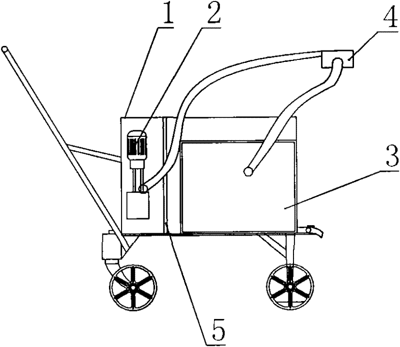
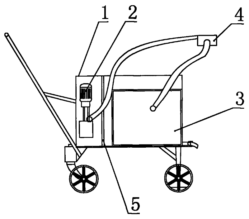
[0008] Such as figure 1 Shown, the present invention comprises oil collection box 1, filter screen 5, oil pump 2, waits for material box 3, waits for ball box 4.

[0009] The above-mentioned oil collection tank 1 is filled with oil, and the middle part is provided with a filter screen 5 that separates the oil collection tank 1 into two cavities. The left cavity is provided with an oil pump 2, and the right cavity is provided with an equal material box 3, and an equal ball Two holes are arranged on the box 4, and two oil pipes are installed respectively, wherein one oil pipe is communicated with the oil pump 2, and the other oil pipe outlet is connected to the waiting material box 3.

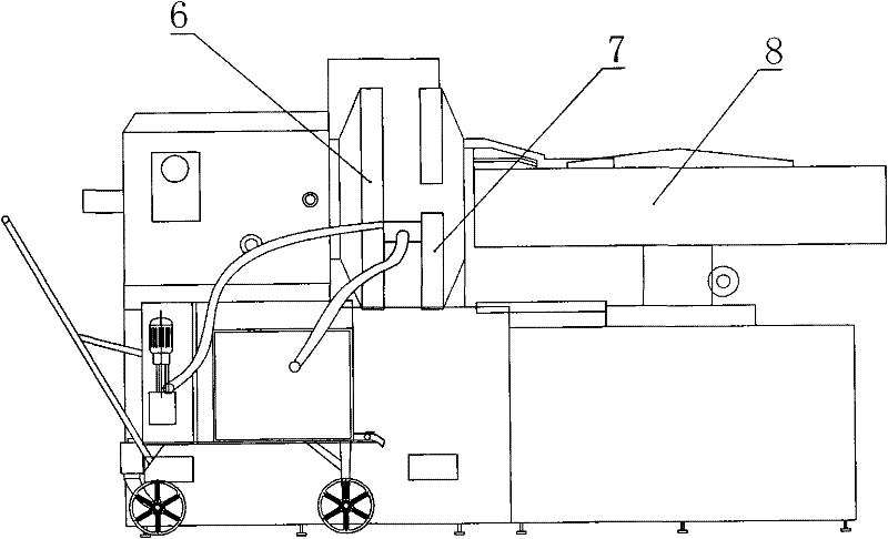
[0010] When used, such as figure 2 As shown, the equal ball box 4 is installed between the dynamic and static grinding plates 6, 7 of the grinding machine when the balls are unloaded, pressurized by the machine tool, and the equal ball box 4 is firmly clamped therein. The oil pump 2 pumps the ...


PUM


Abstract

The invention relates to an automatic ball unloading device for a 3M 7780 grinder, which comprises an oil collection tank, an oil pump, a material catching tank and a ball catching box. The device is characterized in that the oil collection tank is filled with oil; a filtering net is arranged in the middle of the oil collection tank and separates the oil collection tank into tow cavities; the left cavity is internally provided with the oil pump; the right cavity is internally provided with the material catching tank; the ball catching box is respectively connected with two paths of oil pipes;one path of oil pipe is connected with the oil pump, and the other path of oil pipe is connected into the material catching tank. When in use, the ball catching box is installed and tightly clamped between a dynamic grinding plate and a static grinding plate of the grinder by the pressurization of a machine tool when balls are unloaded. The oil pump pumps washing oil in the ball catching box by an oil inlet pipe; at such a moment, the material tray of the grinder is started up reversely, steel balls flow into the ball catching box; and under the action of oil flowing and steel ball flowability, the steel balls flowing into the material catching box, together with the washing oil, flow into the material catching tank in the oil collection tank by another pipe, thereby realizing the function of automatic ball unloading.

Description

technical field [0001] The invention relates to a precision steel ball grinder, in particular to an automatic ball unloading device for a 3M7780 grinder. Background technique [0002] The steel ball finishing process is the last key process in the steel ball processing process. The grinding precision plays a decisive role in the grade of the finished steel ball. The requirements are quite strict. At present, the ball unloading of the grinding machine has been implemented manually. Through a self-made hard paper box similar to a dustpan shape, and a layer of protective plastic bag, the steel balls after grinding are removed from the material. The trays are delivered one by one to the waiting material box. This method of operation, one is that the labor intensity of the workers increases, and the workers feel more tired when a plate of balls is unloaded. The 2nd, operating efficiency reduces, and the unloading process time of a plate ball is about 40-50 minutes, and in unload...

Claims


Application Information

Patent Timeline
Patent Type & Authority Patents(China)
IPC IPC(8): B24B11/02
Inventor 石国庆包建华张建何福艮沈义宏
Owner JIANGSU LIXING GENERAL STEEL BALL
Learn More