
Heat pipe, manufacture method and special equipment

A technology of heat pipes and tubes, which is applied in the field of heat conduction, can solve the problems of shortened service life, reduced effect, intermittent heat conduction, etc., and achieve the effects of resisting impact erosion, avoiding corrosion, and prolonging service life

Inactive Publication Date: 2011-10-05
枣强县天通电力设备有限公司
View PDF0 Cites 0 Cited by
  • Summary
  • Abstract
  • Description
  • Claims
  • Application Information

AI Technical Summary

Problems solved by technology

However, the heat pipes of these two structures have the following defects in the use process and the manufacturing process: First, the heat pipes composed of smooth tubes and finned tubes are directly inserted into boilers or other heat sources, and because they contain a large amount of corrosive gases and dust Particles, so the heat pipe is easily corroded, oxidized and eroded by particles, which greatly shortens its service life; secondly, the new finned tube does increase the contact area and improve the heat transfer efficiency, but in the process of use due to ring or spiral It is very easy to store dust between the shaped fins. In order to reduce the impact of stored dust on the heat conduction efficiency of the heat pipe as much as possible, the dust in the fins must be continuously removed, which will cause interruption of heat conduction, thereby reducing the use of the heat pipe to achieve heat conduction. Effect

Method used

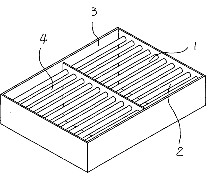
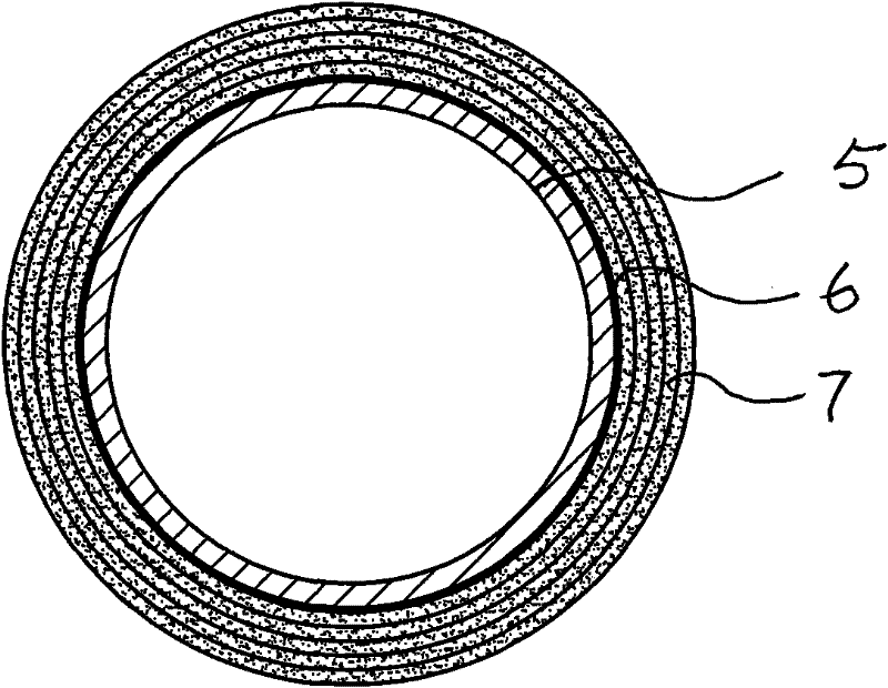
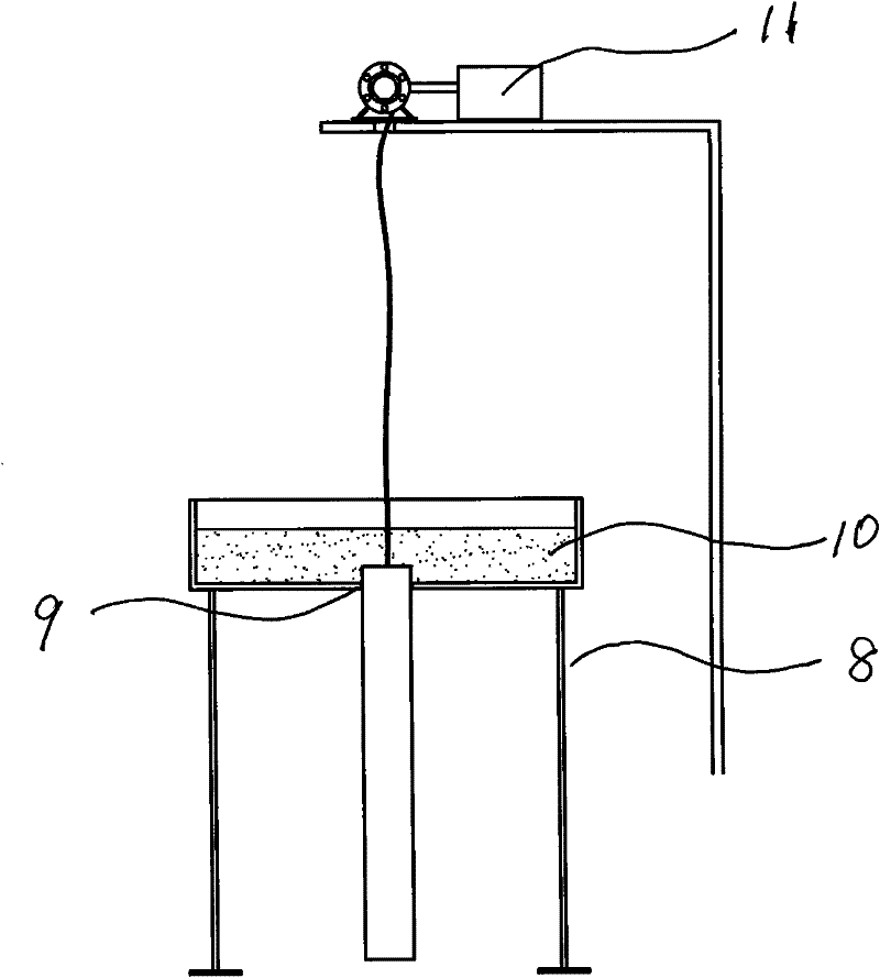

Image

  • Heat pipe, manufacture method and special equipment
  • Heat pipe, manufacture method and special equipment
  • Heat pipe, manufacture method and special equipment

Examples


Embodiment 1

[0030] The first step, the preparation of the bottom glaze layer

[0031] Take out the steel pipe that diameter is 10 millimeters, wall thickness is 1.5 millimeters, and its surface is carried out derusting treatment;

[0032] Then prepare the bottom glaze layer material, that is, take 4.5 kg of silicon dioxide, 0.3 kg of dipotassium oxide, 0.9 kg of boron trioxide, 0.6 kg of sodium fluorosilicate, 0.5 kg of aluminum oxide, 0.7 kg of Disodium oxide and 0.6 kg of calcium fluoride, add water to make its concentration 70%, put the resulting solution into image 3 In the shown container 10, then at an ambient temperature of 25°C, start the traction mechanism 11 set on the fixed frame, so that the steel pipe passes through the hole in the center of the container, and the bottom glaze layer in the container, that is, the bottom glaze layer Coat and hang on the outer wall of the tube; adjust the traction speed of the tube so that the thickness of the bottom glaze layer coated on the...

Embodiment 2

[0037] The first step, the preparation of the bottom glaze layer

[0038] Take out the steel pipe that diameter is 20 millimeters, wall thickness is 2.0 millimeters, and its surface is carried out derusting treatment;

[0039] Then prepare the bottom glaze layer material, namely take 4.0 kg of silicon dioxide, 0.4 kg of dipotassium oxide, 1.2 kg of boron trioxide, 0.7 kg of sodium fluorosilicate, 0.4 kg of aluminum oxide, 0.8 kg of Disodium oxide and 0.6 kg of calcium fluoride, add water to make its concentration 65%, put the resulting solution into image 3 In the shown container 10, then at an ambient temperature of 28°C, start the traction mechanism 11 arranged on the fixed frame, so that the steel pipe passes through the hole in the center of the container and the bottom glaze layer material in the container, that is, the bottom glaze layer material is coated Hang on the outer wall of the tube; adjust the traction speed of the tube so that the thickness of the bottom glaz...

Embodiment 3

[0044] The first step, the preparation of the bottom glaze layer

[0045] Take out the steel pipe that diameter is 25 millimeters, wall thickness is 3.0 millimeters, and its surface is carried out derusting treatment;

[0046] Then prepare the bottom glaze layer material, namely take 4.2 kg of silicon dioxide, 0.5 kg of dipotassium oxide, 1.0 kg of boron trioxide, 0.7 kg of sodium fluorosilicate, 0.5 kg of aluminum oxide, 0.9 kg of Disodium oxide and 0.6 kg of calcium fluoride, add water to make its concentration 72%, put the prepared solution into image 3 In the shown container 10, then at an ambient temperature of 30°C, start the traction mechanism 11 arranged on the fixed frame, so that the steel pipe passes through the hole in the center of the container and the bottom glaze layer material in the container, that is, the bottom glaze layer material is coated Hang on the outer wall of the tube; adjust the traction speed of the tube so that the thickness of the bottom glaze...


PUM

PropertyMeasurementUnit
thicknessaaaaaaaaaa
thicknessaaaaaaaaaa
thicknessaaaaaaaaaa

Abstract

The invention belongs to the technical field of heat conduction, particularly to a heat transferring heat pipe for conducting out heat energy from a furnace body or a heat source in industries such as power generation, chemical engineering, metallurgy and the like, a manufacture method and special equipment. The invention has the main technical scheme that the method comprises the following steps: adopting a container which is provided with holes in the center position and arranged at the middle part of a fixed frame; placing primary glaze materials formed by adding water into silicon dioxide, potassium oxide, boron oxide, sodium fluorosilicate, aluminum oxide, disodium oxide and calcium fluoride into the container; pulling a pipe tube by a traction mechanism for forming slurry to be calcined and formed into a primary glaze layer; then, repeating the steps for adding water into the silicon dioxide, lithium oxide, disodium oxide, potassium oxide, aluminum oxide, nickel oxide and manganese oxide to be stirred for forming glass materials to form slurry on the pipe tube calcined with the primary glaze layer; and preparing the materials into the heat pipe through calcinations. The heatpipe can effectively avoid the corrosion of corrosive gas, and has the characteristic of long service life.

Description

technical field [0001] The invention belongs to the technical field of heat conduction, and relates to a heat transfer heat pipe used in power generation, chemical industry, metallurgy and other industries to export heat energy from a furnace body or a heat source, a manufacturing method and special equipment. Background technique [0002] The heat pipe is used as a conduction and heat dissipation mechanism of the heat source. Its structure includes a tube tube with both ends sealed. A certain amount of working fluid is installed in the tube tube. One end of the tube is inserted into the heat source to heat and absorb heat energy. The phase change of the internal working fluid realizes heat transfer. function. The structure of the heat pipe currently in use includes a light pipe and a finned pipe, that is, a light pipe made of a tube with a smooth outer wall made of metal material, and a heat pipe arranged on the outer wall of the tube in order to increase the heat transfer ...

Claims


Application Information

Patent Timeline
Patent Type & Authority Patents(China)
IPC IPC(8): F28D15/02F28F19/02C23D5/04C23D7/00C03C8/06C03C3/083
Inventor 李树合王秀娥
Owner 枣强县天通电力设备有限公司
Learn More