
Split type stator coil winding method and winding mold device

A stator coil and winding method technology, applied in the field of AC servo permanent magnet synchronous motor production, can solve the problems of unstable motor performance, high labor intensity of workers, and many motor joints, and achieve reduced labor intensity, simple structure, and guaranteed tightness Effect of Degree Requirements

Active Publication Date: 2010-07-21
SHANDONG SHANBO ELECTRIC MACHINE GROUP
View PDF0 Cites 4 Cited by
  • Summary
  • Abstract
  • Description
  • Claims
  • Application Information

AI Technical Summary

Problems solved by technology

If the single-piece stator core teeth winding is still used, during the process of wiring one by one after assembly and tightening, there will be too many wire ends at the outlet end of the winding: 1. Waste of raw materials; 2. High labor intensity and low efficiency for workers ;3. Due to too many motor connectors, it is easy to cause virtual welding, resulting in unstable performance of the motor and many other problems
There is no better solution yet

Method used


Image

  • Split type stator coil winding method and winding mold device
  • Split type stator coil winding method and winding mold device
  • Split type stator coil winding method and winding mold device

Examples


Embodiment 1

[0034] The following takes the motor EM180ST01 as an example to illustrate the processing steps:

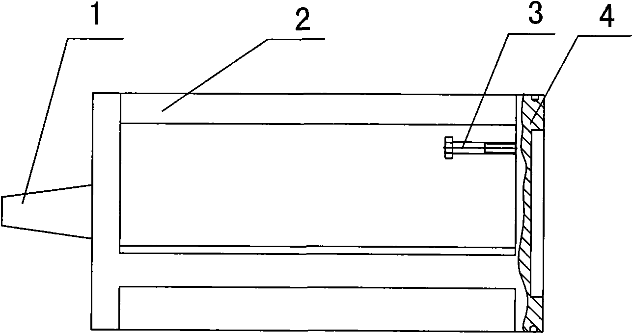
[0035] The AC servo permanent magnet synchronous motor model EM180ST01 has a split stator core composed of 18 split stator core teeth, and each phase has 6 split stator core teeth. The winding diagram is as follows Figure 5 As shown, the electromagnetic scheme is: iron core length L=120mm; wire gauge: Parallel winding; number of turns: 20 turns.

[0036] The winding process of 6 stator tooth coils in each phase of EM180ST01 motor:

[0037] 1. Wrap F-slot insulating paper in the tooth slots of the split stator core teeth, and buckle the ends of the core teeth with insulating end plates.

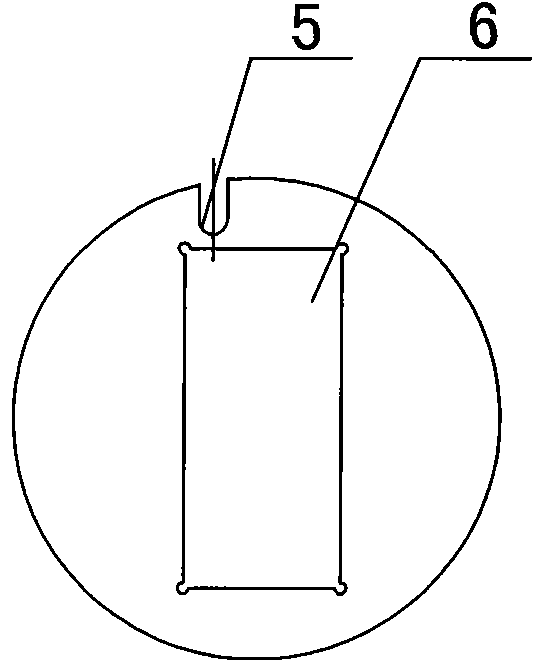
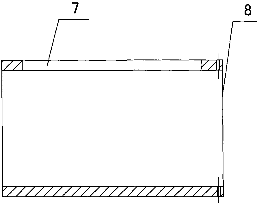
[0038] 2. Put the outer sleeve 8 on the core support 2, and the core support 2 of the winding die device and the first group stator core tooth tip are tightly mounted on the winding machine. The beginning of the winding is drawn from the wire arranging die and passed through the groove of the core supp...


PUM


Abstract

The invention relates to a split type stator coil winding method and a winding mold device, which belong to the manufacture field of an alternating current servo permasyn motor and can be widely applied to industrial automation and military equipment, such as numerical control machines, processing centers, robots, printing machinery, textile machinery, medical machinery, petroleum, chemical engineering, metallurgy, radar antennae and the like. The invention is characterized in that a winding mold device which consists of a winding mold and a winding mold plate matched with the winding mold; sheathing an outer sleeve barrel (8) of the winding mold on a mold core bracket (2); fixing the mold core bracket (2) of the winding mold and the first group of split type stator core teeth on a winding machine; arranging one end of the split type stator core on the mold plate of the winding mold, and pushing tightly by the other end of the winding machine; and directly winding the windings on the first group of split type stator core. The invention has the advantages of large output power, small volume, good low-speed property, strong overloading capability, stable rotation speed and the like.

Description

Technical field [0001] A split stator coil winding method and a winding die device belong to the field of producing AC servo permanent magnet synchronous motors. At present, AC servo permanent magnet synchronous motors use high-performance rare earth permanent magnet materials, which can maintain stable performance in long-term operation, large output power, small size, good low-speed performance, strong overload capacity, and stable speed. Widely used in industrial automation and military equipment, such as CNC machine tools, machining centers, robots, printing machinery, textile machinery, medical equipment, petroleum, chemical, metallurgy, radar antennas, etc. Background technique [0002] Traditional AC servo permanent magnet synchronous motor stators often use mature Y2 series stator punches according to product characteristics. Because the stator punches are integral punching structures, the material utilization rate is low, only about 50%; winding slot full rate Low; work...

Claims


Application Information

Patent Timeline
Patent Type & Authority Applications(China)
IPC IPC(8): H02K15/085H02K15/04
Inventor 于庆彬
Owner SHANDONG SHANBO ELECTRIC MACHINE GROUP
Learn More