
Method for constructing two-station two-line array three-dimensional imaging synthetic aperture radar system

A synthetic aperture radar and three-dimensional imaging technology, which is applied in the field of radar imaging and synthetic aperture radar imaging, can solve the problems of difficulty in obtaining the flight path, large amount of data processing, low control precision, etc. Effect of Accuracy Improvement

Inactive Publication Date: 2010-07-21
UNIV OF ELECTRONICS SCI & TECH OF CHINA
View PDF0 Cites 0 Cited by
  • Summary
  • Abstract
  • Description
  • Claims
  • Application Information

AI Technical Summary

Problems solved by technology

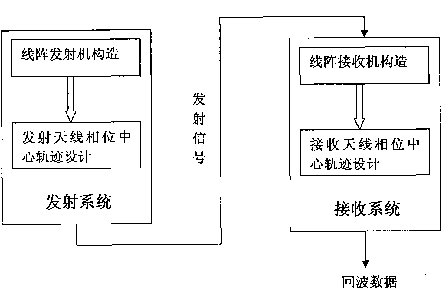
[0009] The purpose of the present invention is to overcome the disadvantages of the existing three-dimensional SAR system, such as low control precision of the antenna phase center trajectory, difficulty in obtaining an arbitrarily set flight path, large power consumption, large data processing volume, and coupling between array elements. A method for constructing a dual-station dual-line array three-dimensional imaging synthetic aperture radar system is provided. The system has the advantages of high antenna phase center control accuracy and all the advantages of the existing dual-station three-dimensional imaging synthetic aperture radar. It reduces power consumption and hardware complexity, overcomes the distance blur effect, and facilitates the realization of three-dimensional imaging of observation scenes

Method used


Image

  • Method for constructing two-station two-line array three-dimensional imaging synthetic aperture radar system
  • Method for constructing two-station two-line array three-dimensional imaging synthetic aperture radar system
  • Method for constructing two-station two-line array three-dimensional imaging synthetic aperture radar system

Examples


Embodiment Construction

[0058] The present invention mainly uses the simulation experiment method to verify the feasibility of the system model, and all steps and conclusions are verified correctly on VC++ and MATLAB7.0. The specific implementation steps are as follows:

[0059] Step 1. Construction of the line array transmitter

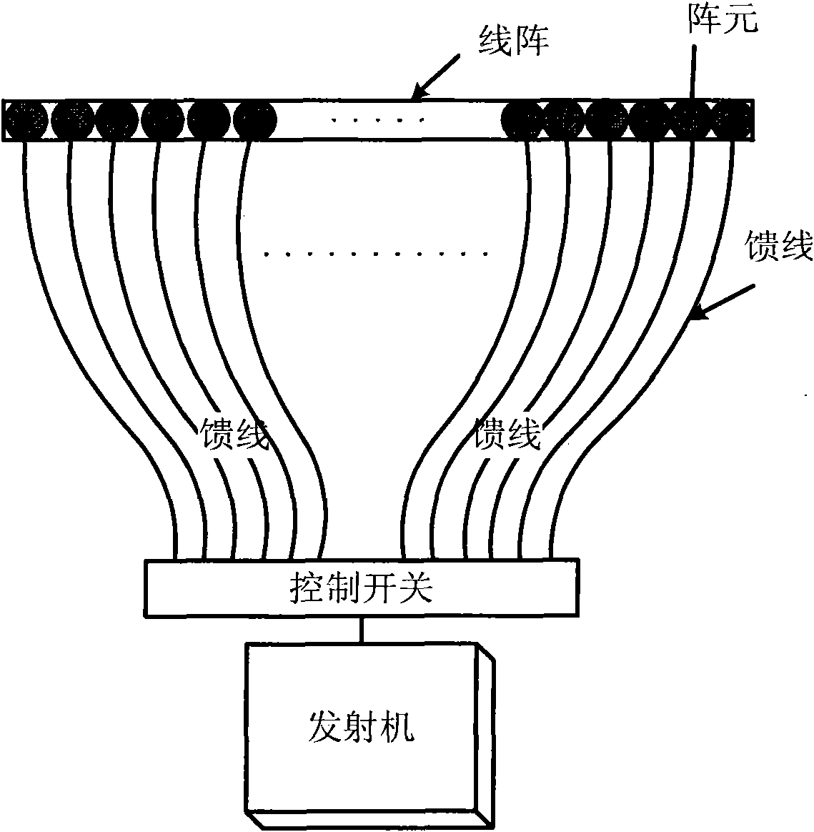
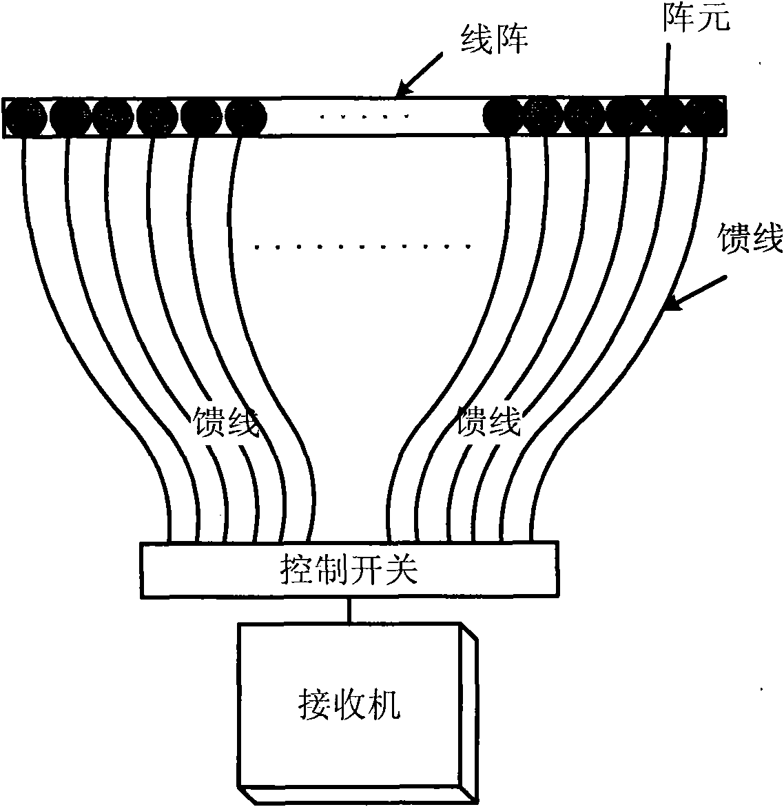
[0060] The linear array transmitter on the launch platform of the dual station dual linear array 3D synthetic aperture radar system includes the following parts: a transmitter, a control switch, 1000 feeders and 1000 linear array feeders. Its system block diagram is attached figure 1 As shown, the control switch is connected to the receiver, the control switch is connected to 1000 line array feeders through 1000 feeders, and the length of the line array is 30. Within a flight aperture, the control switch controls the positions of the feeds that are turned on for each slow time n, n=1...2048, and only one feed is turned on for each slow time n. Each linear array feeder ma...


PUM


Abstract

The invention provides a method for constructing a two-station two-line array three-dimensional imaging synthetic aperture radar system, which utilizes a mode combining a two-station synthetic aperture radar system and a line array system to ensure that both a transmitting antenna and a receiving antenna employ an array feed mode; during each pulse recurrence interval, only one transmitting line array feed is opened to transmit electromagnetic wave signals, and only one receiving line array feed is opened to receive echo data; both the transmitting line array feeds and the receiving line array feeds are controlled by a control switch, thereby realizing artificial control. A single motivation method is adopted to greatly reduce power consumption and hardware complexity, overcome distance blurring effect and facilitate three-dimensional imaging of viewing scenes. The method has the advantages of simple hardware structure, low power consumption, no array element coupling, small data processing capacity and the like.

Description

technical field [0001] The invention belongs to the technical field of radar imaging, in particular to the technical field of synthetic aperture radar (SAR) imaging. Background technique [0002] Synthetic Aperture Radar (SAR) is a high-resolution microwave imaging system, which relies on the relative motion between the radar and the target to form a synthetic array to obtain horizontal high resolution, and uses large bandwidth signals to achieve vertical high resolution. Three-dimensional SAR is based on the conventional SAR horizontal dimension and longitudinal dimension with an additional tangential horizontal dimension, and it also relies on the relative motion between the radar and the target to obtain the tangential horizontal resolution. Three-dimensional imaging is an important feature that distinguishes SAR from other remote sensing imaging systems. [0003] 3D SAR plays an extremely important role: [0004] (1) 3D SAR can accurately image 3D targets at long dista...

Claims


Application Information

Patent Timeline
Patent Type & Authority Applications(China)
IPC IPC(8): G01S13/90G01S7/28
Inventor 张晓玲曾涛王银波师君
Owner UNIV OF ELECTRONICS SCI & TECH OF CHINA
Learn More