
Heat exchanger

A technology of heat exchangers and distributors, applied in evaporators/condensers, lighting and heating equipment, refrigeration components, etc., can solve the problems of unreasonable state of refrigerant and decrease of heat exchange efficiency, etc., and achieve uniformity and stability of refrigerant, Improve the heat exchange efficiency and the effect of reasonable distribution

Active Publication Date: 2010-07-21
SANHUA HANGZHOU MICRO CHANNEL HEAT EXCHANGER +1
View PDF1 Cites 30 Cited by
  • Summary
  • Abstract
  • Description
  • Claims
  • Application Information

AI Technical Summary

Problems solved by technology

This may make the state of the refrigerant leading to the flat tubes from the inner cavity of the header unreasonable, and the bottom liquid refrigerant near the bottom of the header cannot be washed into the relatively upper flat tubes, resulting in a decrease in heat transfer efficiency

Method used


Image

  • Heat exchanger
  • Heat exchanger
  • Heat exchanger

Examples


Embodiment Construction

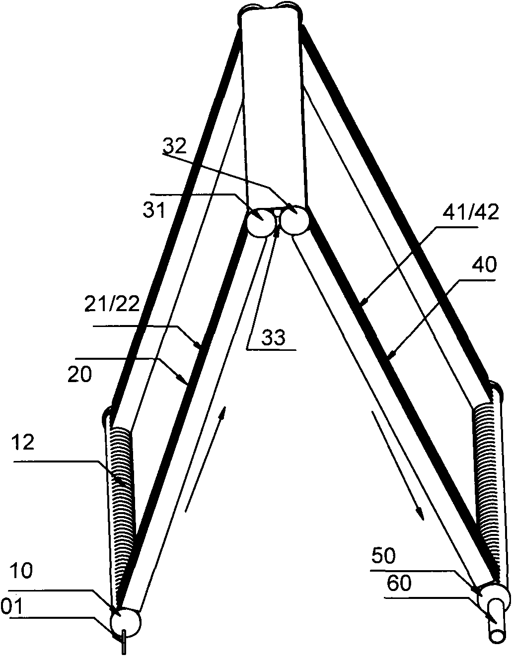
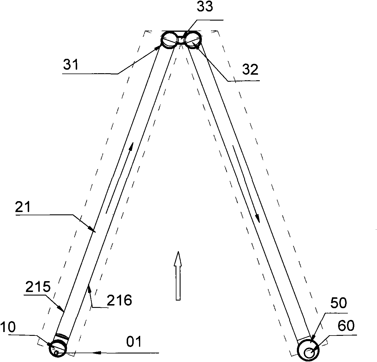
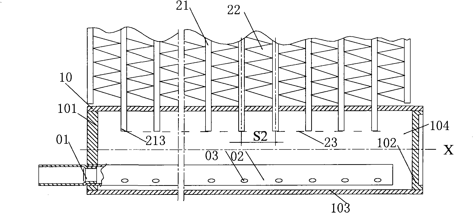
[0038] The core of the present invention is to provide a heat exchanger capable of effectively, stably and reasonably distributing refrigerant, especially a kind of distribution for liquid or vapor-liquid two-phase refrigerant in the heat exchanger used as an evaporator. Through the distributor reasonably arranged and installed in the inlet header, the condensed and throttling refrigerant is reasonably distributed to the corresponding sets of flat tubes for heat exchange according to the heat exchange conditions of the heat exchanger.

[0039] In order to enable those skilled in the art to better understand the solution of the present invention, the present invention will be further described in detail below in conjunction with the accompanying drawings and embodiments.

[0040] figure 1 It is a structural schematic diagram of a heat exchanger used as an evaporator in the present invention. In order to clarify the content of the view, most of the flat tubes and fins inside ar...


PUM


Abstract

The invention discloses a heat exchanger, which comprises an inlet collecting tube. One side of the inlet collecting tube is provided with a plurality of interfaces for flat tubes to be inserted in. Orifices at one end of a plurality groups of flat tubes are respectively inserted in an inner cavity of the inlet collecting tube by the interfaces. A plurality of groups of flat tubes are provided with micro channels for refrigerant to flow. The heat exchanger is also provided with a distributor for distributing the refrigerant. The part of the distributor in the inner cavity of the collecting tube or the distributor in the inner cavity of the collecting tube is positioned on the lower side of the collecting tube so that the refrigerant flowing out of distribution holes disperses the liquid refrigerant on the bottom of the inlet collecting tube to be mixed with each other to guarantee the refrigerant in the micro channels communicated to each groups of flat tubes from the inlet collecting tube is relatively uniform and stable and make the distribution amount of the refrigerant relatively reasonable so as to improve the heat exchange efficiency of the heat exchanger.

Description

technical field [0001] The invention relates to the technical field of heat exchangers, in particular to a parallel flow heat exchanger used as an evaporator. Background technique [0002] A heat exchanger is a device that realizes heat transfer between cold and hot fluids, and is widely used in HVAC, refrigeration and other fields. [0003] The heat exchanger in the prior art generally includes a first header and a second header that are parallel to each other, and the two can usually be arranged in parallel to each other, and there are a plurality of heat exchange flats arranged in parallel between the two. tubes, and fins for fixed heat exchange are provided between the flat tubes for heat exchange. The first header and the second header are respectively provided with a plurality of interfaces for connecting with the flat tubes for heat exchange on the opposite tube walls, and the two ends of the flat tubes for heat exchange respectively pass through the interfaces for t...

Claims


Application Information

Patent Timeline
IPC IPC(8): F25B39/00
Inventor 蒋建龙黄宁杰
Owner SANHUA HANGZHOU MICRO CHANNEL HEAT EXCHANGER
Learn More