
Cross-pulling construction method for soft soil zone with high ground water level

A construction method and groundwater level technology, which can be used in earthwork drilling, soil protection, infrastructure engineering, etc., can solve the problems of large working well size, large impact on the surrounding environment, and high cost

Active Publication Date: 2010-06-23
SHANGHAI GUANGLIAN ENVIRONMENTAL & GEOTECHNICAL ENG CO LTD
View PDF1 Cites 9 Cited by
  • Summary
  • Abstract
  • Description
  • Claims
  • Application Information

AI Technical Summary

Problems solved by technology

Among them, the open cut method has the advantages of simple, fast, economical and safe construction. It is used as the preferred excavation technology in the initial development stage of urban underground tunnels and other projects. Its disadvantage is that excavation has a greater impact on the surrounding environment.
As the pipe jacking method in the underground excavation method, although it can avoid some shortcomings in the open excavation, it also has some shortcomings: the working well must be back against the wall to provide counter force, and the size of the working well must meet the length of the pipe joint, the top The sum of the dimensions of the inlet jack and the backrest means that the size of the working well is large and the cost is high
This method is currently only used in hard soil areas with low groundwater levels. For soft soil areas with high groundwater levels, how to ensure the safety of excavation in a water environment has not been considered.

Method used


Image

  • Cross-pulling construction method for soft soil zone with high ground water level
  • Cross-pulling construction method for soft soil zone with high ground water level
  • Cross-pulling construction method for soft soil zone with high ground water level

Examples


Embodiment Construction

[0018] The embodiments of the present invention will be described in further detail below in conjunction with the accompanying drawings, but the present embodiments are not intended to limit the present invention, and all similar methods and similar changes of the present invention should be included in the protection scope of the present invention.

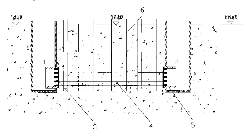
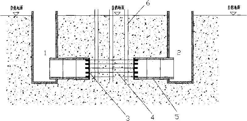
[0019] Depend on Figure 1-Figure 3 As shown, a trenchless construction method for underground pipe culverts in soft soil areas with high groundwater levels provided by the embodiments of the present invention adopts the following steps:

[0020] 1) Use the drilling method or caisson method to set up working wells 1 and 2 underground at both ends of the pipe culvert:

[0021] 2) Use horizontal directional drilling construction technology to lay steel bars or steel cables between the two working wells 1 and 2 along the project axis, and one of the starting wells is used as a working well; For the steel cable, the drilling rig is ...


PUM


Abstract

A cross-pulling construction method for soft soil zone with high ground water level relates to the technical field of underground construction, and aims to solve the technical problem of non-excavating construction in the soft soil zone with high ground water level. The construction method comprises the following steps: 1) setting working wells on the underground on the two ends of a pipe culvert with a well drilling method and a drop shaft sinking method; 2) laying reinforcing steel bars or wire ropes between two work shafts with a horizontal directional drilling technology along the object axes; 3) inlaying precipitation well point pipes between two ground working wells along the project axes; 4) using the two noses on the two ends of the pipe culvert to make the noses and the standard pipe culvert pipe sections on the two sides continuously and oppositely advance in pair; 5) precipitating for the well point pipe which is positioned between the horizontal pipe culverts and adjacent to the pipe culvert; 6) cross-pulling the horizontal pipe culverts to advance to the position of the well point pipe, and pulling out the well point pipe; and 7) cross-pulling the horizontal pipe culverts: continuing the step 4) and the step 6) in cycle until the successful butt join of the pipe culverts. The invention has the characteristic of ensuring the safety of underground construction.

Description

technical field [0001] The invention relates to an underground construction technology, in particular to a non-excavation double-pull construction technology used in soft soil areas with high groundwater levels. Background technique [0002] At present, the construction of underground pipes and culverts generally adopts open cut method, pipe jacking method and so on. Among them, the open cut method has the advantages of simple, fast, economical and safe construction. It is used as the preferred excavation technology in the initial development stage of urban underground tunnels and other projects. Its disadvantage is that excavation has a greater impact on the surrounding environment. As the pipe jacking method in the underground excavation method, although it can avoid some shortcomings in the open excavation, it also has some shortcomings: the working well must be back against the wall to provide counter force, and the size of the working well must meet the length of the pi...

Claims


Application Information

Patent Timeline
IPC IPC(8): E21D9/10E02D3/10E21D1/08
Inventor 方兆昌顾源兴李淑海张志勇王元满王中兵
Owner SHANGHAI GUANGLIAN ENVIRONMENTAL & GEOTECHNICAL ENG CO LTD
Learn More