
Process method for reducing deformation of micro suspension structure in chemically mechanical thinning and polishing process

A thinning polishing, chemical mechanical technology, applied in the direction of polishing machine tools, manufacturing tools, metal processing equipment, etc., can solve the problems of stress reduction, warping deformation, etc., to achieve the goal of reducing warping deformation, improving performance and yield Effect

Active Publication Date: 2011-07-27
NO 55 INST CHINA ELECTRONIC SCI & TECHNOLOGYGROUP CO LTD
View PDF0 Cites 0 Cited by
  • Summary
  • Abstract
  • Description
  • Claims
  • Application Information

AI Technical Summary

Problems solved by technology

[0005] The invention proposes a process method for reducing the deformation of the micro-suspension structure in the chemical mechanical thinning polishing process. method, that is, add an auxiliary support structure to the cavity structure before the suspension structure is released. Due to the effect of the auxiliary support structure, the stress introduced by the cavity structure is greatly reduced during the thinning and polishing process.

Method used


Image

  • Process method for reducing deformation of micro suspension structure in chemically mechanical thinning and polishing process
  • Process method for reducing deformation of micro suspension structure in chemically mechanical thinning and polishing process
  • Process method for reducing deformation of micro suspension structure in chemically mechanical thinning and polishing process

Examples


Embodiment Construction

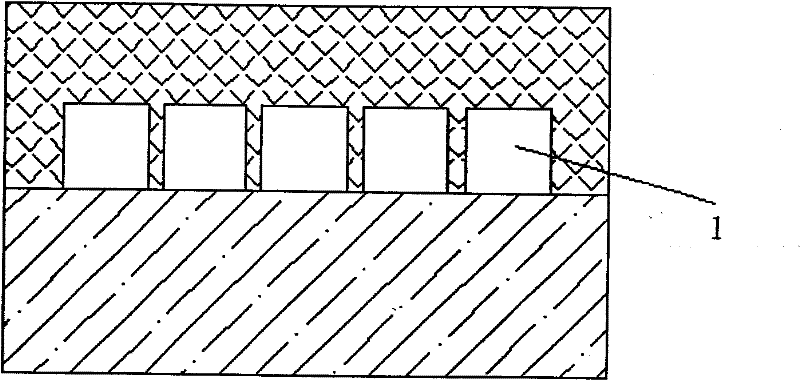
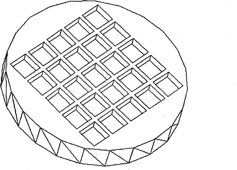
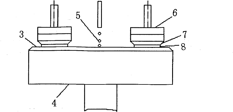
[0018] 1. The process sheet in this process is a two-layer bonded wafer, such as figure 1 As shown, the front side of the wafer that needs to be thinned and polished is the thinned side, and the back side is the bonding side. According to design requirements, wet etching or dry etching is used on the back to form a cavity structure array, such as figure 2 shown. image 3 A schematic diagram of chemical mechanical thinning and polishing is shown. In the chemical mechanical thinning and polishing process of the cavity structure, due to the pressure of the grinding block, the cavity structure will be warped and deformed, such as Figure 4 shown. After thinning and polishing, the cavity structure is released by wet etching or dry etching to form a movable suspension structure that is only connected to the anchor area through thin beams. Due to the stress introduced by thinning and polishing, it cannot be effectively released in the suspension structure. There will be a large ...


PUM


Abstract

The invention provides a process method for reducing deformation of a micro suspension structure in a chemically mechanical thinning and polishing process, which is characterized in that: a wafer for chemically mechanical thinning and polishing is a three-dimensional two-layer wafer formed by a bonding process; according to requirements on the design of an MEMS appliance, the back of the wafer needing to be thinned and polished is provided with a cavity array formed by wet etching or dry etching; the cavity array and the lining wafer form a binding face; the cavity structure array is releasedin a subsequent wet etching or dry etching process to form a moveable suspension structure array supported by a thin girder structure, such as a straight girder or a folded girder; and an ancillary shoring structure is introduced to serve as a compensation structure of the cavity structure before the suspension structure is released. The method has the following advantages that: the process is simple and easily implemented without exerting any influence on the appliance; the warping deformation of the suspension structure is very small; the performance of the MEMS appliance is improved; and the method be widely used for manufacturing micro inertia appliances, micro-fluids, micro radio frequency and other MEMES appliances.

Description

technical field [0001] The invention relates to a process for reducing the deformation of a micro-suspension structure in chemical-mechanical thinning and polishing, which belongs to the field of micro-electro-mechanical system (MEMS) processing, and in particular to a method for reducing the deformation of a three-dimensional micro-mechanical structure with a large-area suspension structure. Chemical Mechanical Thinning of Devices by Polishing Stress and Strain Methods. Background technique [0002] MEMS sensors are usually composed of three-dimensional micro-mechanical structures, detection circuits and signal processing circuits. The microstructure processed by the MEMS bulk silicon process has the advantages of high aspect ratio, large sensitive mass, and high sensitivity, so it is widely used in the processing of three-dimensional microstructures. [0003] The three-dimensional micro-mechanical structure processed by the MEMS bulk silicon process usually uses single cr...

Claims


Application Information

Patent Timeline
Patent Type & Authority Patents(China)
IPC IPC(8): B24B39/06H01L21/302
Inventor 朱健贾世星卓敏刘梅
Owner NO 55 INST CHINA ELECTRONIC SCI & TECHNOLOGYGROUP CO LTD
Learn More