
Method for calculating and locating strip steel head of automatic stepping system of hot continuous rolling coiling machine

A technology for positioning calculation and coiling machine, which is applied to the rolling mill control device, metal rolling, metal rolling and other directions, and can solve the problems of calculation error, coiling failure of strip head, and position mismatch.

Inactive Publication Date: 2010-06-09
WUHAN IRON & STEEL (GROUP) CORP
View PDF0 Cites 40 Cited by
  • Summary
  • Abstract
  • Description
  • Claims
  • Application Information

AI Technical Summary

Problems solved by technology

At this time, the upper and lower pinch rollers are running in the power generation state. During the conversion process, due to the influence of factors such as the material of the strip steel, the oil on the surface of the pinch rollers, and the pressure setting of the pinch rollers is too small, a certain relative slip will be formed between the two. Displacement, resulting in an error in the calculation of the actual position, will also cause a mismatch between the stepping action of the coiling roll and the actual position of the strip head, which will easily cause excessive impact on the equipment or coiling failure of the strip head

Method used


Image

  • Method for calculating and locating strip steel head of automatic stepping system of hot continuous rolling coiling machine
  • Method for calculating and locating strip steel head of automatic stepping system of hot continuous rolling coiling machine
  • Method for calculating and locating strip steel head of automatic stepping system of hot continuous rolling coiling machine

Examples


Embodiment Construction

[0050] The present invention will be further described in detail below in conjunction with the accompanying drawings and specific embodiments.

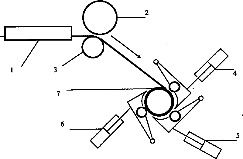
[0051] The layout structure diagram of the process equipment of the coiler is as follows figure 1 As shown, it includes machine front side guide plate 1, upper pinch roller 2, lower pinch roller 3, No. 1 auxiliary roll 4, No. 2 auxiliary roll 5, No. 3 auxiliary roll 6, and main drum 7. Among them, the front side guide plate 1 of the machine is installed on the fixed stand on the ground, the upper pinch roller 2, the lower pinch roller 3, the No. The drums 7 are installed as unit equipment on the frame of the main body of the coiler respectively.

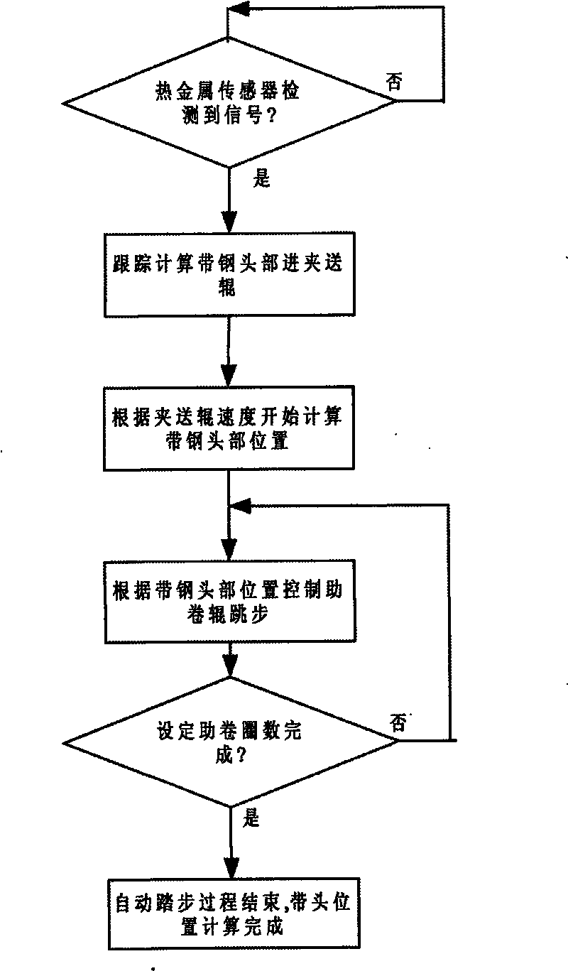
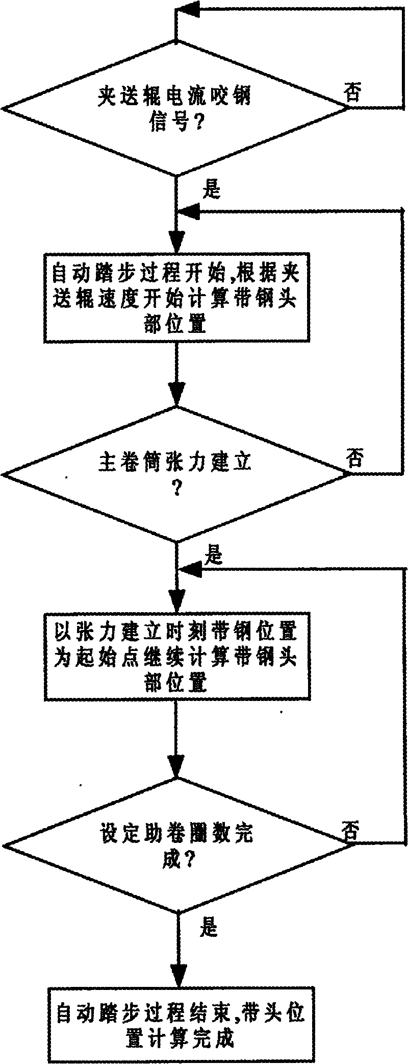
[0052] like image 3 As shown, the automatic stepping system strip head positioning calculation method of the hot rolling coiler of the present invention comprises the following steps:

[0053] S1. Acquisition of the steel bite signal when the strip steel enters the pinch roller.

[0054...


PUM


Abstract

The embodiment of the invention provides a method for calculating and locating the strip steel head of an automatic stepping system of a hot continuous rolling coiling machine, comprising the following steps of: detecting whether the strip steel enters a pinch roll, wherein when the strip steel is detected to enter the pinch roll, the automatic stepping process begins, the head position of the strip steel is calculated according to the speed of a lower pinch roll; detecting the tension of a main drum, if the tension of the main drum is not established, the head position of the strip steel is continuously calculated according to the speed of a lower pinch roll, if the tension of the main drum is established, the head position of the strip steel is continuously calculated by using the momentary position of the strip steel head at the main drum at the tension establishing moment as a start point; detecting whether the set wrapping number of turns is finished, if the set wrapping number of turns is not finished, the head position of the strip steel is continuously calculated by using the head position of the strip steel at the tension establishing moment as a start point; if the set wrapping number of turns is finished, the automatic stepping process stops and the calculation for the head position of the strip steel is finished. The invention can effectively overcome the defects that an on-site hot metal detector and an optoelectronic detecting element are subject to various on-site interferences.

Description

technical field [0001] The invention relates to a method for calculating the positioning of the strip head of an automatic stepping system of a hot continuous rolling coiler. Background technique [0002] In the production process of modern hot-rolled strip steel, when the strip steel head passes through the final stand of the finishing rolling area and is thrown away, it is cooled by laminar flow to reach the process temperature, and the strip steel needs to be coiled continuously by a coiler. The practice of steel rolling production shows that the production status of the coiler directly affects the production capacity of the rolling mill operation line and the final quality of the finished strip, and affects the smooth progress of the subsequent process. The coiler of the hot rolling production line is a complex system integrating machinery, electricity, pneumatics and hydraulics, and works in harsh environments such as shock vibration, high temperature, water and scale. ...

Claims


Application Information

Patent Timeline
IPC IPC(8): B21B37/00B21B38/00
Inventor 梅勇
Owner WUHAN IRON & STEEL (GROUP) CORP
Learn More