
Continuously variable transmission of snowmobile

A technology of infinitely variable transmission and snowmobile, which is applied to portable lifting devices, components with teeth, belts/chains/gears, etc. It can solve the problem of small centrifugal force of driving wheel rollers, inability to effectively transmit torque, small thrust of moving discs, etc. problem, to achieve the effect of large inclination angle, reliable and effective automatic adjustment, and slow and stable movement

Inactive Publication Date: 2010-05-12
重庆永发科技有限公司
View PDF0 Cites 10 Cited by
  • Summary
  • Abstract
  • Description
  • Claims
  • Application Information

AI Technical Summary

Problems solved by technology

Since the large-displacement snowmobile has to bear heavy load, high speed, and long-term operation (transportation, patrol), if the structure of the motorcycle continuously variable transmission is adopted, the centrifugal force of the driving wheel roller is small, and the thrust on the moving plate is small. , can not produce reliable and stable thrust to the moving disc, effectively adjust the distance between the moving disc and the fixed disc, especially when starting and driving at low speed, the centrifugal force of the roller is smaller, the torque cannot be effectively transmitted, and the transmission efficiency is low; however, If the hydraulic mechanism used in automobiles is used to apply axial hydraulic pressure to the driving and driven wheels to push the moving plate, the structure is complicated and the cost is too high

Method used


Image

  • Continuously variable transmission of snowmobile
  • Continuously variable transmission of snowmobile
  • Continuously variable transmission of snowmobile

Examples


Embodiment Construction

[0021] Below in conjunction with accompanying drawing and embodiment the present invention will be further described:

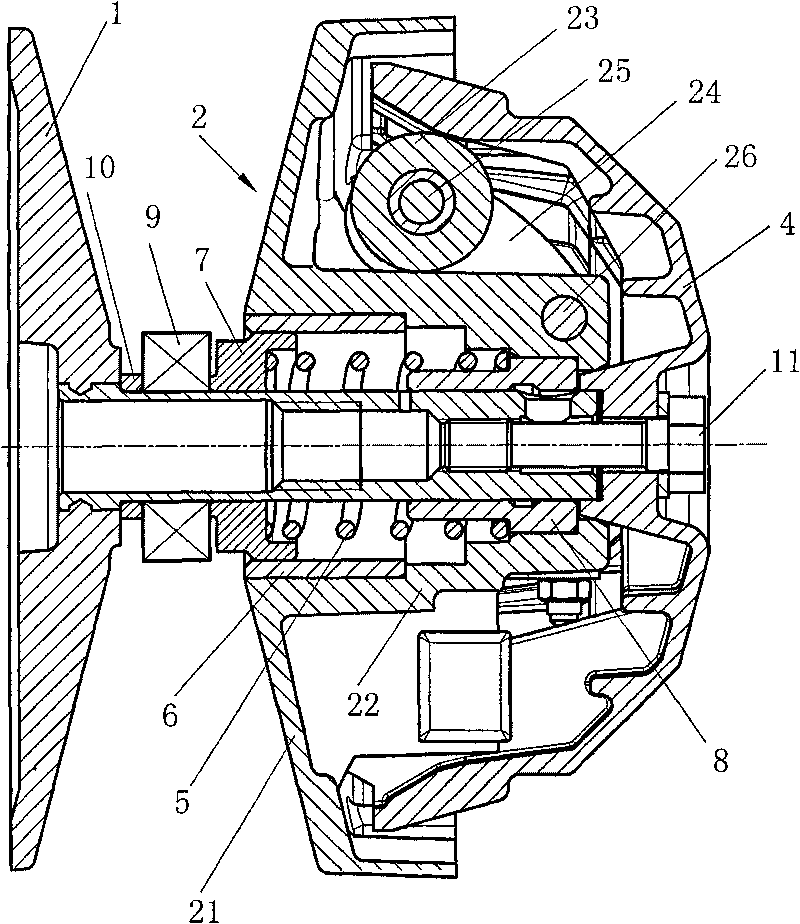
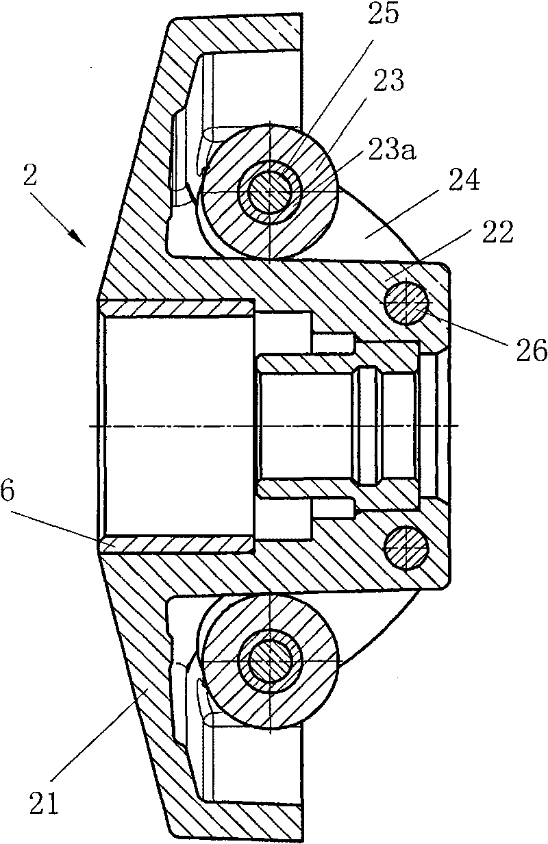
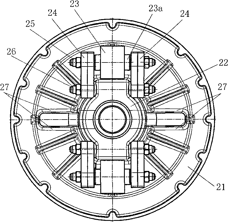
[0022] The present invention is a continuously variable transmission for snowmobiles, which includes a driving wheel, a driven wheel and a transmission belt connecting the driving wheel and the driven wheel. The structure of the driven wheel is basically the same as that of the driven wheel of a motorcycle stepless changer. The spring compression type requires that after the diameter of the wheel groove of the driving wheel becomes larger, the spring force of the driven wheel is overcome by the movement of the transmission belt to the outer circle of the driving wheel (because the length of the transmission belt remains unchanged), so that the driven plate of the driven wheel moves, thereby The diameter of the wheel groove of the driven wheel is reduced to realize the speed change. Such as figure 1 As shown, the driving wheel is mainly composed of a fixed pl...


PUM


Abstract

The invention discloses a continuously variable transmission (CVT) of a snowmobile. The CVT comprises a driving wheel, a driven wheel and a transmission belt which is used for connecting the driving wheel with the driven wheel. The driving wheel is provided with a fixed disc with a conical surface, a movable disc and a central shaft. The CVT is characterized in that the central shaft arranged between the fixed disc and the movable disc is sheathed with a rolling bearing; the periphery of the movable disc is uniformly provided with 2-4 idler wheels; two sides of each idler wheel are symmetrically provided with counterweight arms; one end of the central shaft, far away from the fixed disc, is fixed with a cover; the idler wheels on the movable disc always prop against the internal surface of the cover under the action of a compressive spring; and positions on the internal surface of the cover, corresponding to the idler wheels, are provided with idler wheel slideways. The CVT has simple structure and low manufacture cost, can play a function of turning off the power and replacing a clutch when the transmission belt falls on the ball bearing, has greater centrifugal force at a certain rotation speed, and leads the driving wheel to quickly and forcibly push the fixed disc, thus reliably and effectively changing the groove size of the driving wheel and the driven wheel automatically, and realizing speed change.

Description

technical field [0001] The present invention relates to a transmission mechanism, and more particularly, to a continuously variable transmission for a snowmobile. Background technique [0002] The continuously variable transmission system is driven by two transmission wheels whose diameter can be changed, and a transmission belt set on the two transmission wheels. Small scooters generally use a continuously variable transmission device, which relies on the driving wheel to generate centrifugal force through the centrifugal roller, forcing the driven wheel to overcome the spring resistance in the driven wheel, so that the driven wheel becomes smaller and the driving wheel becomes larger, thereby realizing speed change. The continuously variable transmission driving wheel of a motorcycle includes a fixed disc with a tapered surface and a moving disc. The fixed disc is fixed at one end of the central shaft, and the moving disc is slipped on the central shaft. The end of the mov...

Claims


Application Information

Patent Timeline
Patent Type & Authority Applications(China)
IPC IPC(8): F16H9/12F16H55/36
Inventor 蒋国峰
Owner 重庆永发科技有限公司
Learn More