
Fast constant temperature microreactor

A micro-reactor and reactor technology, applied in the field of reactors, can solve the problems of long thermal equilibrium time, unfavorable miniaturization and micro-analysis, large consumption of heating and cooling, etc., achieve rapid temperature change and precise constant temperature control, and meet high-precision measurement Effect of usage requirements, high control precision and speed

Inactive Publication Date: 2010-04-21
INST OF CHEM CHINESE ACAD OF SCI
View PDF1 Cites 21 Cited by
  • Summary
  • Abstract
  • Description
  • Claims
  • Application Information

AI Technical Summary

Problems solved by technology

Since the water bath uses a large amount of water, and the specific heat capacity of water is also large, the response of the water temperature to the control signal is slow. Therefore, the system can only achieve the temperature control of the water in the water bath after a long period of time, and in actual use In general, the waiting time is not long, which leads to the difference between the actual temperature of the water bath solution and the set temperature
At the same time, the system does not directly measure the temperature of the sample, and its constant temperature is not carried out on the sample, so it can only ensure that the water in the water bath is constant temperature. Therefore, this system is only suitable for situations where the temperature accuracy is not high.
[0004] 2. Since a large amount of heat exchange medium is used in the traditional method, a large amount of heat needs to be consumed during temperature control to realize the heating and cooling of the medium. Therefore, it takes a long time for heat balance to reach the set target temperature. To achieve high precision, it will take more time to wait for the system temperature to stabilize
This system is suitable for slow temperature changes, but not suitable for control environments with rapid temperature changes
[0005] 3. Traditional indirect heat exchange control generally requires a large amount of heat conduction medium, large volume and many accessories, which is not conducive to the needs of miniaturization and micro analysis
The disadvantage of this system is that the sample cell has only one sample inlet and outlet, which makes it necessary to re-clean the sample cell when changing samples. At the same time, the volume of the sample cell is limited by the size of the stirring magnet, which cannot further reduce the volume.

Method used


Image

  • Fast constant temperature microreactor
  • Fast constant temperature microreactor
  • Fast constant temperature microreactor

Examples


Embodiment 1

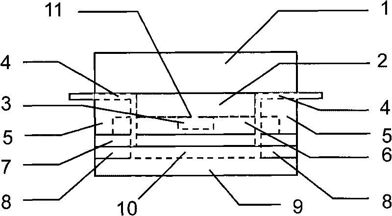
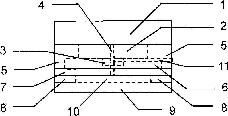
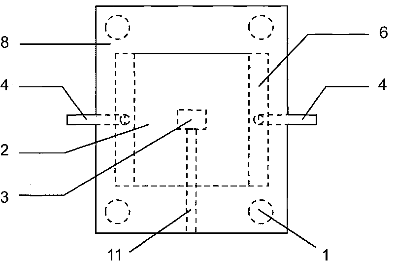
[0026] The structural schematic diagram of the fast constant temperature microreactor is as follows: figure 1 shown. The sample cell 10 is a closed cuboid space formed by an inert thin layer 7 with a thickness of 0.2mm, a sealing gasket 8 and an inert flat plate 9, and the size of the sample cell is 20mm×20mm×0.5mm. Glass is selected as the material for forming the inert thin layer, and silicone rubber PDMS sold by Dow Corning (Dow Corning) as the material for forming the sealing gasket is selected as Sylgard 184. During temperature control, the heat conduction block 6 is heated or refrigerated by the temperature control element 2 to provide a uniform temperature environment for the test solution in the sample cell 10 . Copper is selected as the material for the heat conduction block 6 , and a semiconductor heating and cooling chip sold by Qinhuangdao Fulianjing Electronics Co., Ltd., model number FPH1-1707NC, is selected as the temperature control element 2 .

[0027] The tem...

Embodiment 2

[0036] This embodiment is a fast constant temperature reactor using a microfluidic chip, and its structural schematic diagram is shown in Figure 4 and Figure 5 shown; Figure 4 for the side view, Figure 5 For top view. Among them, 13 is a microfluidic chip, 14 is a microchannel in the microfluidic chip, and the outlet and inlet of the channel communicate with the catheter respectively. The style of the microchannel is set according to actual needs and is not limited by this figure.

[0037] In this embodiment, the microfluidic chip 13 is used to replace the inert thin layer, sealing gasket and inert flat plate in Embodiment 1, and the microchannel area 14 in the microfluidic chip is used as the sample pool of the reactor. The microfluidic chip 13 is a glass microchannel chip, which is obtained through glass wet etching technology and heat sealing technology in this field. The specific operation steps are as follows: first, copy the desired channel pattern to the surfac...


PUM


Abstract

The invention discloses a fast constant temperature microreactor. The fast constant temperature microreactor comprises a sample cell and at least one sample inlet and outlet arranged on the top of the sample cell, wherein the bottom of the sample cell is provided with an inert slab or a microfluidic chip, the top of the sample cell is provided with an inert thin layer, and a sample cell wall formed by a seal cushion is arranged between the inert slab and the inert thin layer; heatconducting blocks and temperature sensors are arranged on the inert thin layer, and the temperature sensors are covered in the heatconducting blocks; temperature control elements are arranged on the heatconducting blocks, and radiating blocks are arranged on the temperature control elements; the side walls of the heatconducting blocks and the side walls of the temperature control elements are covered by insulating housings; and the sample inlet and outlet of the sample cell is communicated with the outside by pipelines. The microreactor has compact size, can be used as a sample cell for a surface plasma resonator, a resonance light scattering apparatus and other analytical instruments to realize the fast temperature change and the accurate constant temperature control of samples in controlled elements, and can meet the operating requirement of high accuracy measurement on temperature-sensing biological samples.

Description

technical field [0001] The invention relates to a reactor, in particular to a rapid constant temperature micro-reactor. Background technique [0002] In the existing reactor, the constant temperature of the reaction sample is realized by indirect heat balance. Generally, a constant temperature water bath box or a water pump is used, and the reaction pool is immersed in the water bath pool during work, and the water bath pool indirectly controls the temperature in the reaction pool by controlling the temperature of the water body around the reaction pool. There are following deficiencies in this type of technology: [0003] 1. It is difficult to meet the needs of high-precision temperature control analysis or synthesis. Because the traditional constant temperature water bath or oil bath controls the temperature of the water (or oil) for heat exchange, that is, the temperature sensing element detects the temperature of the heat exchange medium rather than the temperature of ...

Claims


Application Information

Patent Timeline
Patent Type & Authority Applications(China)
IPC IPC(8): G01N21/03G01N21/09G01N1/28B01L7/02
Inventor 陈义张轶鸣
Owner INST OF CHEM CHINESE ACAD OF SCI
Learn More