
Plate-type heat-exchange efficient energy-saving furnace

A high-efficiency, energy-saving, plate-type heat exchange technology, applied in the field of boilers, can solve the problems of small heating surface, slow boiler water flow, large volume, etc., and achieve the effects of increased interaction time, extended water heat exchange path, and large heat exchange area.

Inactive Publication Date: 2010-04-07
吉林市恒新汽车滤清器制造有限责任公司
View PDF0 Cites 1 Cited by
  • Summary
  • Abstract
  • Description
  • Claims
  • Application Information

AI Technical Summary

Problems solved by technology

[0002] There are many types of existing heating boilers, which are generally high in pollution, high in energy consumption, and low in thermal efficiency. Adding a dust collector to passively eliminate smoke, dust and desulfurize, the noise is huge, which consumes electric energy and increases the cost of use; in order to solve the small problem of the heating surface, the method of extending the live line process and adding tubes is adopted, which not only increases the burden on the heating system due to the excess water in the boiler, it is not easy Rapid heating also causes the boiler water to flow slowly, which is prone to scaling and shortens the service life; due to the boiler water exchange and the cross-arrangement of the fire tubes, the sticky soot and scale hanging up during operation cannot be easily removed, which continues to reduce the thermal efficiency of the boiler; so far , there are no literature reports and practical applications of plate heat exchange high-efficiency energy-saving furnaces

Method used


Image

  • Plate-type heat-exchange efficient energy-saving furnace
  • Plate-type heat-exchange efficient energy-saving furnace
  • Plate-type heat-exchange efficient energy-saving furnace

Examples


Embodiment Construction

[0027] The present invention will be further described below using the drawings and examples.

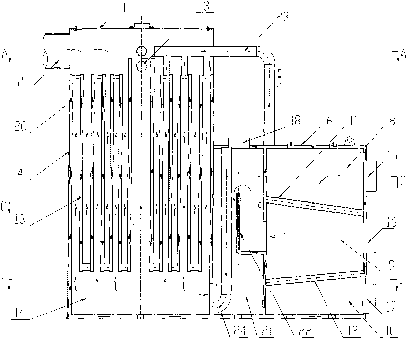
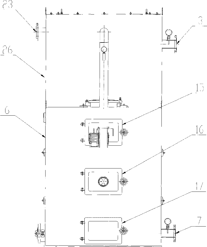
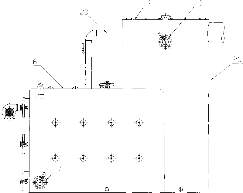
[0028] refer to Figure 1-4 , the plate type heat exchange high-efficiency energy-saving furnace of the present invention includes a water jacket furnace body 6 and a water jacket outer cylinder 4, and a feed combustion chamber 8, a combustion chamber 8 and a slag removal chamber are sequentially arranged in the water jacket furnace body 6 from top to bottom 10. A feed combustion chamber furnace door 15 is provided on the water jacket furnace body 6 where the feed combustion chamber 8 is located, and a combustion chamber furnace door 16 is provided on the water jacket furnace body 6 where the combustion chamber 9 is located. The water jacket furnace body 6 where the chamber 10 is located is provided with a slag removal door 17 . The water jacket furnace body 6 between the feed combustion chamber 8 and the combustion chamber 9 is provided with a feed combustion chamber water tube g...


PUM


Abstract

The invention relates to a plate-type heat-exchange efficient energy-saving furnace. The furnace comprises a water jacket-type furnace body and a water jacket outer cylinder, a water inlet, a water outlet, a flue gas exhaust port and an exhaust port of a plate-type heat exchanger, and is characterized in that a feeding combustion chamber, a combustion chamber and a smoke and fire baffling chamber inside the water jacket furnace body as well as a flue gas chamber and the flue gas exhaust port inside the plate-type heat exchanger are communicated to form a smoke and fire to-and-fro baffling heating path; the plate-type heat exchanger consists of the water jacket outer cylinder and a plurality of water jacket cylinders arranged inside the water jacket outer cylinder and communicated end to end in turn; the water jacket furnace body is communicated with the water jacket outer cylinder of the plate-type heat exchanger; and the water inlet arranged on the water jacket furnace body, a water jacket of the water jacket furnace body, a pipeline arranged inside the smoke and fire baffling chamber, the water jacket outer cylinder of the plate-type heat exchanger, the water jacket cylinders and the water outlet are communicated end to end in turn to form a water to-and-fro baffling heat-exchange path. The plate-type heat-exchange efficient energy-saving furnace has the advantages of large heating area, safe combustion, complete heat exchange, high thermal efficiency, no environmental pollution, low cost, and the like.

Description

technical field [0001] The invention relates to the field of boilers, and relates to a high-efficiency and energy-saving plate heat exchange furnace. Background technique [0002] There are many types of existing heating boilers, which are generally high in pollution, high in energy consumption, and low in thermal efficiency. Adding a dust collector to passively eliminate smoke, dust and desulfurize, the noise is huge, which consumes electric energy and increases the cost of use; in order to solve the small problem of the heating surface, the method of extending the live line process and adding tubes is adopted, which not only increases the burden on the heating system due to the excess water in the boiler, it is not easy Rapid heating also causes the boiler water to flow slowly, which is prone to scaling and shortens the service life; due to the boiler water exchange and the cross-arrangement of the fire tubes, the sticky soot and scale hanging up during operation cannot be...

Claims


Application Information

Patent Timeline
IPC IPC(8): F24H1/44
Inventor 李刚王东升
Owner 吉林市恒新汽车滤清器制造有限责任公司
Learn More