Method for removing nitrogen oxides in waste gas or flue gas

A nitrogen oxides and waste gas technology, applied in chemical instruments and methods, separation methods, dispersed particle separation, etc., can solve the problems that have not yet seen ideal reports, the direct oxidation rate of NO is slow, and the conversion rate per unit time is low. Abundant raw materials, low removal cost, easy to popularize and popularize in a large area

Inactive Publication Date: 2010-03-10
XIANGTAN UNIV
View PDF0 Cites 5 Cited by
  • Summary
  • Abstract
  • Description
  • Claims
  • Application Information

AI Technical Summary

Problems solved by technology

Due to the low concentration of NO in the flue gas, relying on the O in the flue gas 2 The rate of direct oxidation of NO is very slow, the conversion rate per unit time is low, and it has no industrial application value
The gas phase catalytic oxidation method can greatly increase the oxidation rate of NO under the action of a catalyst. Extensive research has been carried out at home and abroad, but the difficulty is that it is difficult to develop a 2 and H 2 Catalysts poisoned by O have not yet seen ideal reports
O 3 , KMnO 4 、K 2 Cr 2 A lot of research has been done on the direct oxidation of NO by O7 and other oxidants, and there are also a small number of industrial devices in operation, but the cost is too high and it is difficult to promote it on a large scale.

Method used


Image

  • Method for removing nitrogen oxides in waste gas or flue gas
  • Method for removing nitrogen oxides in waste gas or flue gas
  • Method for removing nitrogen oxides in waste gas or flue gas

Examples


Embodiment 1

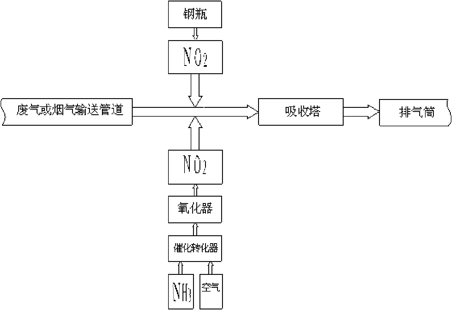
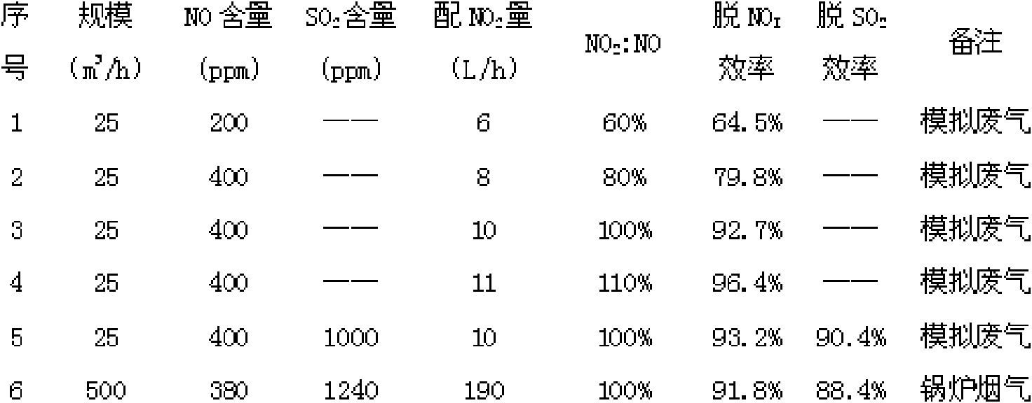
[0038] 25 cubic meters per hour (m 3 / h) simulated exhaust gas, the simulated exhaust gas contains 200ppm NO, and the rest is air, with 6 liters per hour (L / h) NO 2 gas, NO 2 The volume ratio to NO is 60%, and the lime slurry with a mass fraction of 10% is used as the absorbent, the circulation rate is 25L / h, and the NO x The removal efficiency is 64.5%.

Embodiment 2

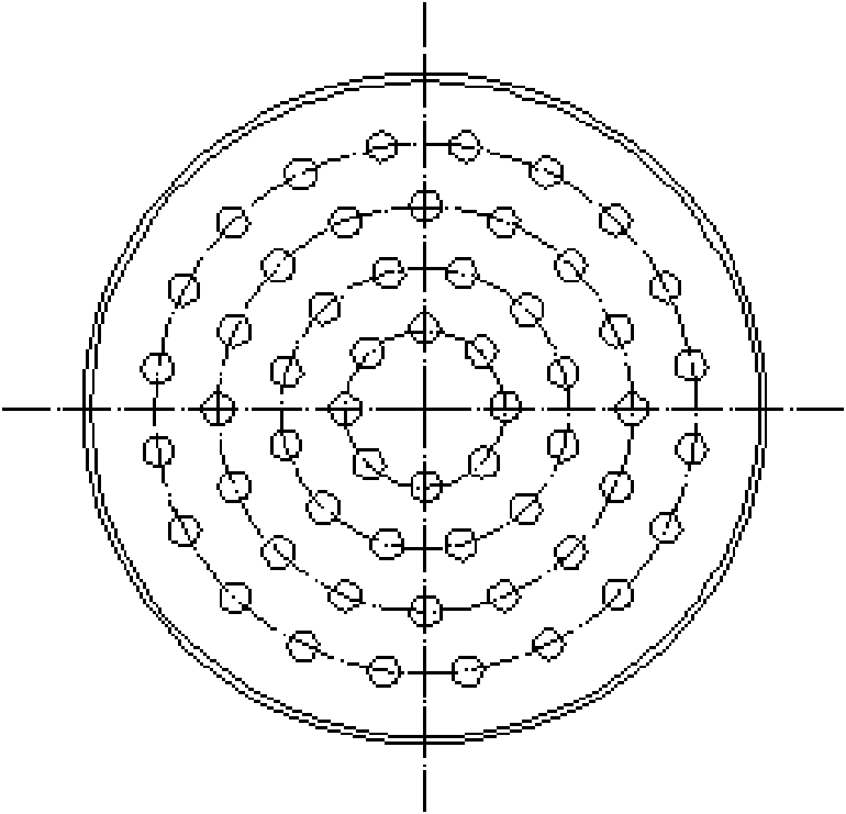
[0040] In an absorption tower with a diameter of 100mm, a built-in 2-layer sieve plate, an opening rate of 17%, and a small hole diameter of 2mm, the 25m 3 / h simulated exhaust gas, the simulated exhaust gas contains 400ppm of NO, the rest is air, with 8L / h NO 2 gas, NO 2 The volume ratio to NO is 80%, and the lime slurry with a mass fraction of 10% is used as the absorbent, the circulation rate is 25L / h, and the NO x The removal efficiency is 79.8%.

Embodiment 3

[0042] In an absorption tower with a diameter of 100mm, a built-in 2-layer sieve plate, an opening rate of 17%, and a small hole diameter of 2mm, the 25m 3 / h simulated exhaust gas, 400ppm NO in the simulated exhaust gas, the rest is air, with 10L / h NO 2 gas, NO 2 The volume ratio to NO is 100%, and the lime slurry with a mass fraction of 10% is used as the absorbent, the circulation rate is 25L / h, and the NO x The removal efficiency is 92.7%.


PUM


Abstract

The invention relates to a method for removing nitrogen oxides in waste gas or flue gas, comprising the following steps of: connecting an absorbing tower in series on a waste gas or flue gas conveyingpipeline at the front of an exhaust pipe, adding NO2 at the front of the absorbing tower and introducing the NO2 into flue gas or waste gas flow for mixing after being metered, then using a removingagent to treat the mixed gas by absorbing and removing of the absorbing tower with the removing agent and then discharging the mixed gas from the exhaust pipe; and adopting the following technical scheme: connecting the absorbing tower in series on the waste gas or flue gas conveying pipeline, connecting a nitrogen dioxide cylinder laterally at the front of the tower to directly add NO2 into the waste gas or flue gas conveying pipeline or connect a catalytic converter and an oxidizer laterally at the front of the absorbing tower, oxidizing NH3 released by a liquid ammonia cylinder into NO2 which is then mixed in the flue gas or waste gas conveying pipeline, and then carrying out absorbing and removing treatments by the absorbing tower. The method overcomes the defects that the existing method for denitrifying and denitrating waste gas or flue gas has complex treating technique, high cost, large waste and higher condition and requirements on treated flue gas and waste gas and the like,is applicable to denitration of flue gas and waste gas of nitrogen oxides containing nitric oxide as main material, and is especially applicable to removing nitrogen oxides of flue gas of a boiler.

Description

technical field [0001] The invention relates to a method for removing nitrogen oxides in waste gas or flue gas. Background technique [0002] Nitrogen oxide NO X It is one of the main air pollutants. It mainly comes from the flue gas produced by fossil fuel combustion and the exhaust gas emitted during the use of nitric acid and nitrate. Compared with the mobile characteristics of motor vehicle exhaust, they are collectively referred to as stationary sources. Stationary NO X There are three main pollution control methods: (1) fuel denitrification; (2) low NO X Combustion; (3) Exhaust gas or flue gas denitrification. NO in combustion flue gas X fuel type NO X and thermal NO X Composed of thermal NO X Dominant; the former is the nitrogen in the fuel when the fuel is combusted by the oxygen O in the air 2 generated by oxidation, while the latter is nitrogen in the combustion air N 2 O in the air being oxidized under the condition of high temperature in the combustion c...

Claims


Application Information

Patent Timeline
IPC IPC(8): B01D53/56B01D53/78B01D53/86
Inventor 张俊丰曾炯巍
Owner XIANGTAN UNIV
Why Eureka
Try Eureka