
Kilohertz common light path satellite laser ranging (SLR) optical device

A technology of satellite laser ranging and optical devices, which is applied in measuring devices, measuring distances, line-of-sight measurements, etc., can solve the problems of large rotational inertia of rotating mirrors, affecting echo reception, echo reflection loss, etc., and achieves improved ranging Success rate, improving ranging accuracy, and improving the effect of ranging ability

Inactive Publication Date: 2010-02-17
YUNNAN ASTRONOMICAL OBSERVATORY CHINESE ACAD OF SCI
View PDF0 Cites 17 Cited by
  • Summary
  • Abstract
  • Description
  • Claims
  • Application Information

AI Technical Summary

Problems solved by technology

However, the moment of inertia of the rotating mirror is relatively large, and the dynamic pressure generated by the continuous periodic change of the spindle angular velocity will affect the echo reception, especially when the spindle speed is too high. On the one hand, it will deflect the normal of the mirror surface of the rotating mirror, resulting in loss of echo reflection; on the other hand, it will drive the entire optical system to vibrate, seriously affecting the stability of the optical system
At the same time, the laser emission must be synchronized with the rotating mirror in this optical path, and the limitation of the spindle speed of the rotating mirror also limits the laser emission frequency accordingly. Therefore, the ranging frequency of the common optical path ranging method in the world is generally lower than 100 Hz. , kilohertz frequency ranging has not yet been implemented

Method used


Image

  • Kilohertz common light path satellite laser ranging (SLR) optical device
  • Kilohertz common light path satellite laser ranging (SLR) optical device
  • Kilohertz common light path satellite laser ranging (SLR) optical device

Examples


Embodiment Construction

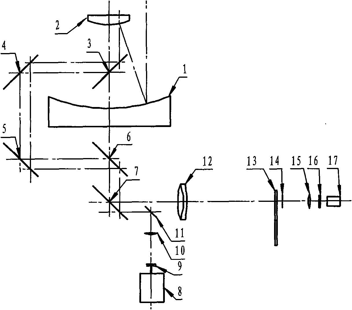
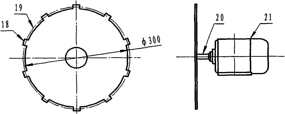
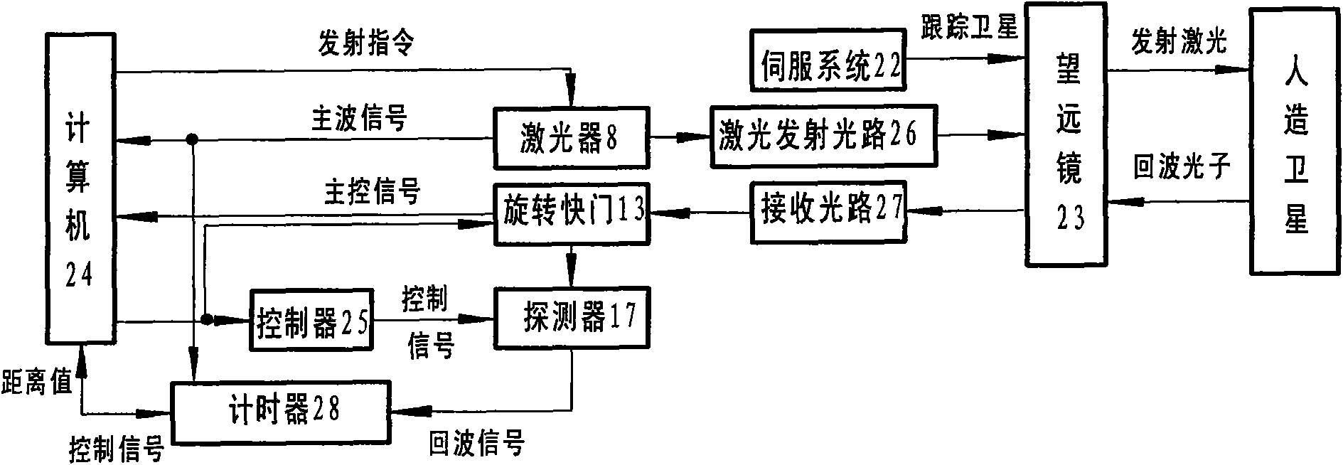
[0026] Such as figure 1 As shown, the kilohertz common optical path satellite laser ranging optical path is composed of three parts: the reflective ranging telescope, the laser emitting optical path, and the echo receiving optical path.

[0027] Among them, the ranging telescope is composed of a parabolic primary mirror 1, a parabolic secondary mirror 2 and a folding axis reflector 3.4.5.6.7, and the focal lengths of the parabolic primary mirror 1 and the parabolic secondary mirror 2 are F M , F s , the focal ratio is F M / F s , two confocal mirrors form an afocal system. The telescope tracks the artificial satellite during ranging, and is responsible for laser emission and echo collection at the same time: when the laser is emitted, the laser beam is expanded F M / F s After multiple times, it is launched to the satellite; when the echo is received, the echo beam is compressed by F M / F s After doubling, it is transferred to the echo receiving optical path.

[0028] In...


PUM

PropertyMeasurementUnit
Diameteraaaaaaaaaa

Abstract

The invention relates to a kilohertz common light path satellite laser ranging (SLR) optical device, belonging to laser ranging systems and comprising a reflective ranging telescope, a laser emissionlight path and an echo-receiving light path. The ranging telescope comprises a paraboloidal primary mirror, a paraboloidal secondary mirror and an elbow reflector; the laser emission light path comprises a kilohertz laser, a negative lens, a positive lens and a docking mirror; wherein the negative lens and the positive lens are formed a laser-expanding structure capable of adjusting a divergence angle; a coupling lens and a collimating lens in the echo-receiving light path are confocal to be formed an afocal system; the diameter of a compressed echo ray behind the collimating lens is matched with the pupil-entrance diameter of a single-photon detector; a rotary shutter is arranged in front of a focus of the echo coupling lens; an iris diaphragm is arranged on the focus of the echo couplinglens; and an optical filter is arranged in front of the single-photon detector. The kilohertz common light path SLR optical device selects a ranging frequency within 1-4 KHz, has high ranging accuracy and great echo amount and improves the ranging capability and the ranging level of the system.

Description

technical field [0001] The invention belongs to a laser ranging system, in particular to a satellite laser ranging system with a common optical path that uses the same telescope to emit laser light and receive echoes. Background technique [0002] Satellite Laser Ranging (SLR for short) is mainly used for research in the fields of precise orbit determination of artificial satellites, astro-geodynamics, geodesy, and relativity verification. Laser pulses are sent to the artificial satellite of the reflector, and after being reflected by the satellite reflector, they are received by the telescope of the ground ranging station, and the round-trip time interval t of the laser pulse from the ground measuring station to the artificial satellite is accurately measured, and the ground distance is calculated by the speed of light C The distance L between the station and the artificial satellite is as follows: [0003] L = 1 2 ...

Claims


Application Information

Patent Timeline
IPC IPC(8): G01S17/08G01C3/04
Inventor 伏红林冯和生李祝莲何少辉何超
Owner YUNNAN ASTRONOMICAL OBSERVATORY CHINESE ACAD OF SCI
Learn More