
Method and instrument for measuring shock ground resistance of transmission line tower

A technology for impacting grounding resistance and power transmission lines. It is used in grounding resistance measurement, instruments, measuring devices, etc. It can solve the problems of low signal-to-noise ratio, low accuracy, small size, etc., and achieve strong anti-interference ability and high accuracy. , light weight effect

Inactive Publication Date: 2010-02-17
WUHAN NARI LIABILITY OF STATE GRID ELECTRIC POWER RES INST
View PDF0 Cites 30 Cited by
  • Summary
  • Abstract
  • Description
  • Claims
  • Application Information

AI Technical Summary

Problems solved by technology

The disadvantage of this method is that it is difficult to establish a mathematical and physical model, and the solution is complicated and cumbersome, and different grounding devices have different mathematical and physical models, which has poor versatility and the results cannot be verified
[0004] 2. The simulation test is mainly aimed at the centralized grounding body, and its size is small, so it cannot completely simulate the real situation
[0005] 3. The impact grounding resistance is obtained by multiplying the measured power frequency grounding resistance by the impact coefficient. Since the impact grounding resistance is obtained by indirect means, the reliability of the result is poor
[0006] 4. Estimate based on empirical formulas. Although the calculation is simple and convenient, its disadvantage is that the accuracy is low and it can only be used for estimation
[0007] Corresponding to the above several measurement and calculation methods, the impact grounding resistance measuring instruments designed by some universities and scientific research institutes currently produce impulse current amplitudes below 5A, the signal-to-noise ratio is not high, and the measurement accuracy is not high. They are mainly used as Experimental research does not yet meet the conditions for engineering promotion and application

Method used


Image

  • Method and instrument for measuring shock ground resistance of transmission line tower
  • Method and instrument for measuring shock ground resistance of transmission line tower

Examples


Embodiment Construction

[0019] Below in conjunction with accompanying drawing and specific embodiment the utility model is described in further detail.

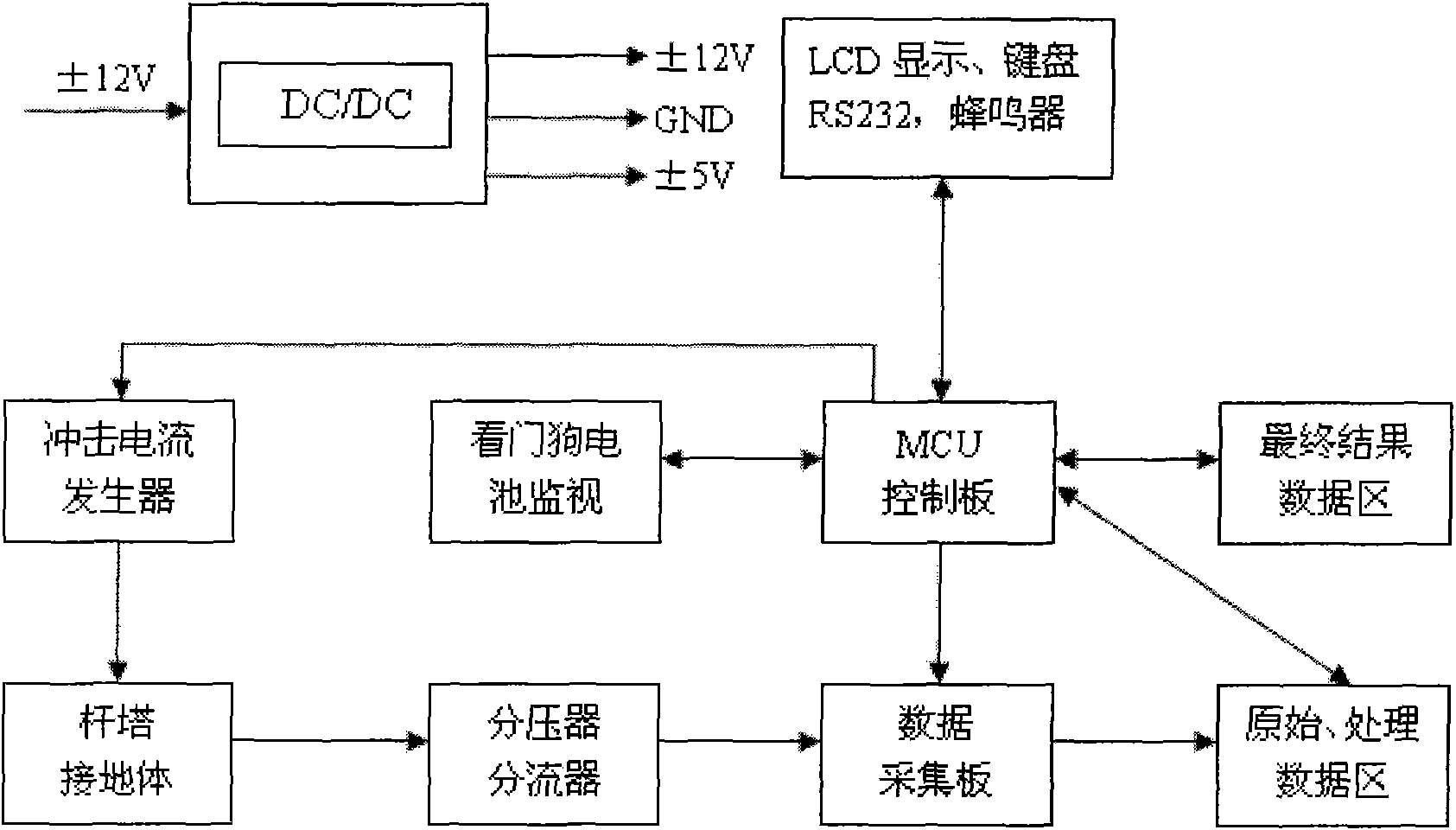
[0020] like figure 1 As shown, the core part of the transmission line tower impact grounding resistance measurement method of the present invention includes four parts: an impulse current generator, a high-speed data acquisition board, an MCU control board, and a data display. When working, an impulse current for measurement is generated by the impulse current generating device and injected into the ground, and the voltage and current components on the voltage divider and shunt are collected by the data acquisition device in real time, and transmitted to the MCU control board for data processing, and Carry out linear amplification calculation to find the voltage response of the grounding body under the action of standard lightning current, and obtain the equivalent voltage u m , current peak i m , and finally according to the engineering definitio...


PUM


Abstract

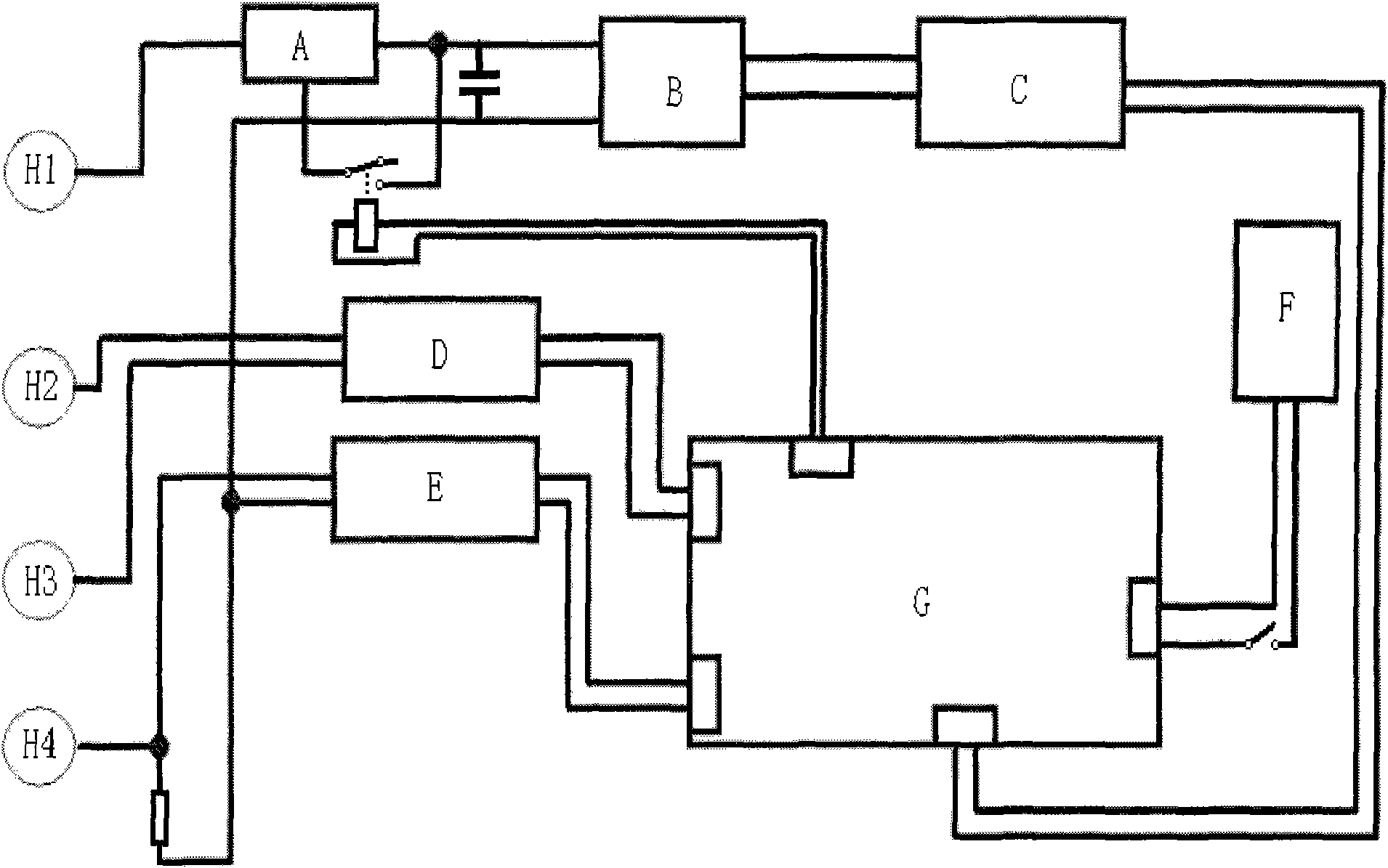
The invention relates to a method and an instrument for measuring the shock ground resistance of a transmission line tower. The method comprises the following steps: generating incident current by a shock current generator and filling the incident current into the ground; collecting the grounding voltage and the current of the tower by a data collecting device; carrying out treatment and linear amplification on the collected data by an MCU control panel to solve the voltage response of a grounding body under the action of standard lightning current and obtain an equivalent voltage um and a current peak im; and finally, obtaining the shock ground resistance of the tower according to a formula of Rch=um / im. The instrument comprises a current pole lead connecting plug, a grounding device connecting plug, controlled silicon, a charging board, a voltage-multiplying generator, a voltage collecting board, a current collecting board, a battery and a main control board, wherein the current polelead connecting plug is connected with the charging board and the voltage-multiplying generator and then connected to the main control board; the controlled silicon is connected to a circuit in series; the voltage collecting board is connected with a voltage pole lead connecting plug, the grounding device connecting plug and the main control board; the current collecting board is connected with the current pole lead connecting plug, the grounding device connecting plug and the main control device; and the battery is directly connected to the main control board.

Description

technical field [0001] The invention relates to a method for measuring tower impact grounding resistance and related instruments. Specifically, it is an impact grounding resistance measuring method and measuring instrument which are easy to carry, convenient to operate, accurate in measurement and strong in anti-interference. Background technique [0002] Before the present invention proposes, there are following several methods in this field to the measurement and calculation of impact grounding resistance: [0003] 1. On the basis of theoretical analysis, establish a mathematical and physical model for the specific grounding device, and calculate the impact grounding resistance of the grounding device by solving partial differential equations or differential equations. The disadvantage of this method is that it is difficult to establish a mathematical and physical model, and the solution is complex and cumbersome, and different grounding devices have different mathematica...

Claims


Application Information

Patent Timeline
IPC IPC(8): G01R27/20G01R27/08
Inventor 谭进袁明仁范冕杜雪松
Owner WUHAN NARI LIABILITY OF STATE GRID ELECTRIC POWER RES INST
Learn More