Stabilized voltage supply convertor with long service life and low electromagnetic interference

A stabilized power supply, low electromagnetic technology, applied in the direction of adjusting electrical variables, converting equipment with intermediate conversion to AC, converting DC power input to DC power output, etc., can solve the problem of increasing losses, increasing costs, and increasing converters Volume and other issues, to achieve the effect of improving efficiency, convenient debugging, and reducing volume

Inactive Publication Date: 2011-08-17
MORNSUN GUANGZHOU SCI & TECH
View PDF0 Cites 0 Cited by
  • Summary
  • Abstract
  • Description
  • Claims
  • Application Information

AI Technical Summary

Problems solved by technology

[0003] Although this circuit can realize soft switching, high efficiency, and uncomplicated control, it also has some disadvantages: it must be controlled by variable frequency to achieve stable voltage output, which leads to many problems related to frequency changes, such as EMI testing and rectification , and a resonant inductor needs to be connected in series with the primary side of the piezoelectric ceramic transformer to achieve soft switching in a relatively wide frequency range
The existence of the resonant inductance will undoubtedly increase the volume of the converter, increase the cost, and increase the loss. It will be very meaningful if the resonant inductance can be removed to ensure that the circuit can still have the same function.

Method used


Image

  • Stabilized voltage supply convertor with long service life and low electromagnetic interference
  • Stabilized voltage supply convertor with long service life and low electromagnetic interference
  • Stabilized voltage supply convertor with long service life and low electromagnetic interference

Examples


Embodiment Construction

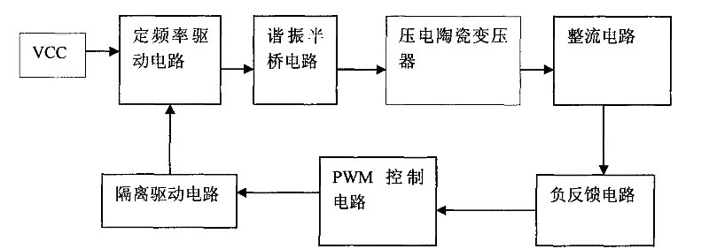
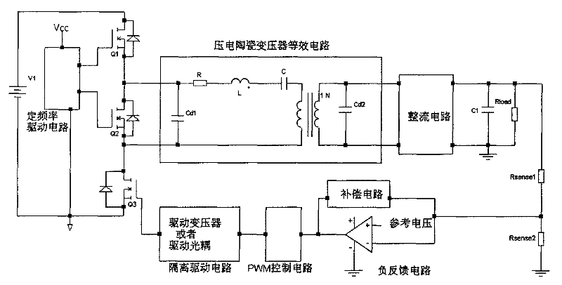
[0018] Such as figure 2 As shown, it mainly includes the following components: 1) fixed frequency drive circuit part: mainly composed of a fixed frequency drive chip or a square wave generator with a fixed frequency and duty cycle, and a switch tube Q3; 2) a resonant half bridge circuit, There are two switch tubes Q1 and Q2; 3) Piezoelectric ceramic transformer: composed of piezoelectric ceramic transformer; 4) Rectifier circuit part: mainly composed of rectifier circuit, capacitor C1, load resistance Rload and sampling resistance Rsense1, Rsense2; 4 ) Negative feedback circuit part: mainly composed of a reference voltage source and compensation circuit part; 5) PWM control circuit part (common PWM chip such as UC3843, etc.); 6) Isolated drive circuit part: drive transformer or drive optocoupler. The fixed-frequency driving circuit is connected between the resonant half-bridge circuit and the isolated driving circuit; the PWM control circuit is connected between the negative ...


PUM


Abstract

The invention discloses a stabilized voltage supply convertor with long service life and low electromagnetic interference, comprising a resonance half-bridge circuit, a piezoelectric ceramics transformer, a rectification output circuit, a degenerative circuit and an isolation drive circuit. The invention is characterized in that the stabilized voltage supply converter also comprises a drive circuit with a fixed frequency and a PWM control circuit, wherein, the drive circuit with a fixed frequency is connected between the resonance half-bridge circuit and the isolation drive circuit, and the PWM control circuit is connected between the degenerative circuit and the isolation drive circuit; the output of the resonance half-bridge circuit is connected with the input end of the piezoelectric ceramics transformer which is output by the rectification circuit; the output feedback sampling voltage of the supply convertor is connected with the PWM control circuit via the degenerative circuit; the PWM output of the PWM control circuit controls the driving duty ratio of the isolation drive circuit which drives the on-off or cut-off of the drive circuit with a fixed frequency; thus, the resonance half-bridge circuit controlled by the drive circuit with a fixed frequency is in the mode of intermittent working, and the time ratio of the intermittent working is determined by the driving duty ratio of the isolation drive circuit.

Description

technical field [0001] The invention relates to a power converter, in particular to a long-life, low-electromagnetic-interference regulated power converter. Background technique [0002] Piezoelectric ceramic transformers have been increasingly used in the field of switching power supplies due to their outstanding performance advantages. At present, one of the more common ways is to apply the resonant half-bridge circuit to the piezoelectric ceramic transformer power converter. The circuit structured as figure 1 As shown, it includes: 1) resonant half-bridge circuit, composed of two series-connected switch tubes Q1 and Q2; 2) piezoelectric ceramic transformer: composed of piezoelectric ceramic transformer; 3) rectifier circuit part: mainly composed of rectifier circuit, capacitor C1, load resistance R load and sampling resistor R sense1 , R sense2 Composition; 4) Negative feedback circuit part: mainly composed of a reference voltage source and compensation circuit part; ...

Claims


Application Information

Patent Timeline
Patent Type & Authority Patents(China)
IPC IPC(8): H02M3/28H02M3/335
Inventor 龚晟黄江剑张红军
Owner MORNSUN GUANGZHOU SCI & TECH
Why Eureka
Try Eureka