
Sample reservoir for carrying out in-situ characterization on crystallization process of molecular sieve based catalyst, and use method thereof

A technology of catalyst and molecular sieve, which is applied in the direction of material analysis using wave/particle radiation, electromagnetic means, material analysis using radiation diffraction, etc., to achieve a wide range of applications

Active Publication Date: 2010-01-20
SHANXI INST OF COAL CHEM CHINESE ACAD OF SCI
View PDF0 Cites 11 Cited by
  • Summary
  • Abstract
  • Description
  • Claims
  • Application Information

AI Technical Summary

Problems solved by technology

[0003] Unfortunately, due to the limitations of window materials on X-ray transparency and the sealing of the sample cell under high temperature and high pressure conditions, people have previously used synchrotron X-rays to study the structure of catalysts, but still aimed at offline sample

Method used


Image

  • Sample reservoir for carrying out in-situ characterization on crystallization process of molecular sieve based catalyst, and use method thereof
  • Sample reservoir for carrying out in-situ characterization on crystallization process of molecular sieve based catalyst, and use method thereof
  • Sample reservoir for carrying out in-situ characterization on crystallization process of molecular sieve based catalyst, and use method thereof

Examples


Embodiment 1

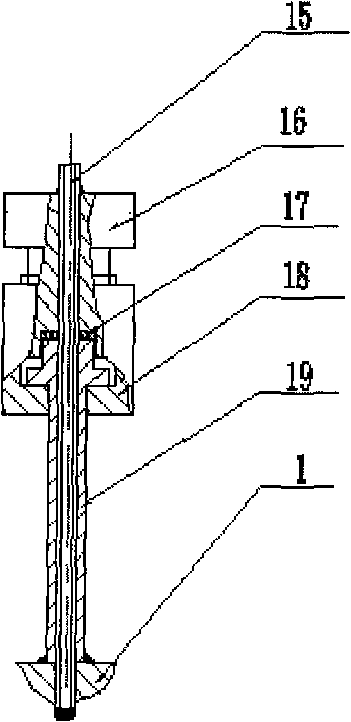
[0034] The pool body 1 is a cylinder with stepped holes, the small holes are through holes, and the stepped large holes at both ends of the pool body 1 are symmetrical; the pool body 1 has a radial circular hole leading from the outer surface to the axis in the radial direction. There is an annular inner core 8 in the small hole of the body 1, and a radial circular hole is arranged in the radial direction of the inner core 8, and the radial circular hole of the inner core 8 communicates with the radial circular hole of the pool body 1, and the inner core 8 has two Each side has a circular window 4,9, and the inner core 8 forms a cavity with the two circular windows 4,9; the sum of the thicknesses of the inner core 8 and the two circular windows 4,9 communicates with the pool body The length of the hole is equivalent, and the end faces of the two stepped holes of the pool body 1 are respectively provided with an annular gasket 3,10; Circular hole 14, there is a long hole 13 in ...

Embodiment 2

[0048] Embodiment 2: wherein the sample imported is a microemulsion molecular sieve precursor; the material of the windows 4,9 is boron nitride ceramics, and the thickness is 2mm; the material of the gaskets 3,10 is polyimide; the thickness of the inner core 8 0.5mm; the material of the gasket 17 is polytetrafluoroethylene; the control temperature is 280°C, and the pressure is self-boosting pressure. All the other are with embodiment 1.

Embodiment 3

[0049] Embodiment 3: wherein the sample introduced is a reverse micellar molecular sieve precursor; the material of the windows 4 and 9 is metal beryllium with a boron nitride thin film deposited on the inner surface, and the thickness is 0.8mm; the material of the gaskets 3 and 10 is polyamide imide; the thickness of the inner core 8 is 2 mm; the material of the gasket 17 is polyimide; the controlled temperature is 300° C., and the pressure is a self-boosting pressure. All the other are with embodiment 1.


PUM

PropertyMeasurementUnit
Thicknessaaaaaaaaaa
Thicknessaaaaaaaaaa
Thicknessaaaaaaaaaa

Abstract

A sample reservoir for carrying out in-situ characterization on crystallization process of a molecular sieve based catalyst comprises a reservoir body, a press ring, a sealing pad, a window piece, a reservoir cover, a fastening element, an inner core and a thermocouple component. The sample reservoir allows X rays to pass through and studies the crystallization process of the molecular sieve based catalysts in an in-situ online manner by using XAFS (x-ray absorption fine structure), XRD (X-ray diffraction), SAXS (small angle X-ray scattering), SAXS / WAXS (small angle X-ray scattering and wide angle X-ray scattering) under the conditions of 0-300 DEG C and 0-3 MPa. The change of the catalyst structure is monitored during the processes.

Description

technical field [0001] The invention belongs to a catalyst in-situ characterization device and method, in particular to a sample cell and method for in-situ characterization of molecular sieve catalyst crystallization process based on synchrotron radiation X light source Background technique [0002] The unique pore structure, high specific surface area and hydrothermal stability of zeolite molecular sieve make it widely used in the fields of catalysis, adsorption and separation. In recent years, the development of nano zeolites has further broadened the application of zeolites to new fields such as electronic materials, optical materials, drug carriers, and environmental protection. The development of various self-assembly technologies provides new means for the directional synthesis of ideal molecular sieves. Changes in the size or shape of zeolite molecular sieves will cause huge differences in their own catalytic activity, selectivity and stability. The identification ...

Claims


Application Information

Patent Timeline
IPC IPC(8): G01N23/083G01N23/20G01N23/201G01N23/203G01K7/02
Inventor 王建国王国富董梅秦张峰吉向飞
Owner SHANXI INST OF COAL CHEM CHINESE ACAD OF SCI
Learn More