Eureka AIR delivers breakthrough ideas for toughest innovation challenges, trusted by R&D personnel around the world.

Supersonic condensation and cyclone separation device

A cyclone separation device, supersonic technology, applied in cyclone devices, devices whose axial direction of cyclone remains unchanged, solidification and other directions, can solve the problem of large total pressure loss, poor flow field uniformity, affecting separation efficiency and pressure. Recycling efficiency and other issues

Inactive Publication Date: 2010-01-06
XI AN JIAOTONG UNIV
View PDF12 Cites 46 Cited by
  • Summary
  • Abstract
  • Description
  • Claims
  • Application Information

AI Technical Summary

Problems solved by technology

The first generation of this technology is to use supersonic wings to achieve swirling flow. Domestic patents in this area are like CN1896184A. The disadvantages are that the shock wave resistance and flow resistance are relatively large, and the uniformity of the flow field is poor, which is not conducive to the growth of droplets and causes separation. low efficiency
The second-generation supersonic separation technology of Twister BV uses guide vanes to generate swirl at the entrance, and controls the swirl intensity by controlling the change of the average radius of the flow channel. The disadvantage is that it is not suitable for small flows In the case of small flow, the gap of the annular channel is very small, resulting in serious wall friction loss, and because of the existence of a large amount of low-energy fluid in the boundary layer, the separation efficiency and pressure recovery efficiency are affected
The existing natural gas supersonic dehumidification technology cannot operate under the condition of small flow rate or the separation efficiency is low when the flow rate is small, and the total pressure loss is large. However, the rapid development of my country's economy and the gradual emphasis on environmental protection will inevitably affect the high heat of natural gas. Therefore, the development of natural gas dehumidification technology adapted to the characteristics of my country's onshore gas fields will surely bring huge economic and social benefits

Method used


Image

  • Supersonic condensation and cyclone separation device
  • Supersonic condensation and cyclone separation device
  • Supersonic condensation and cyclone separation device

Examples


Embodiment Construction

[0015] The present invention will be described in further detail below in conjunction with the accompanying drawings.

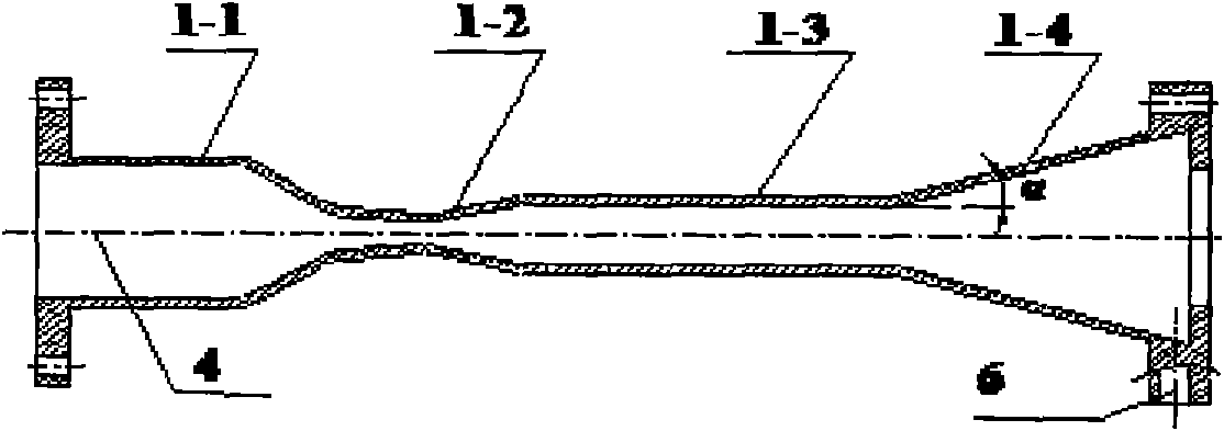
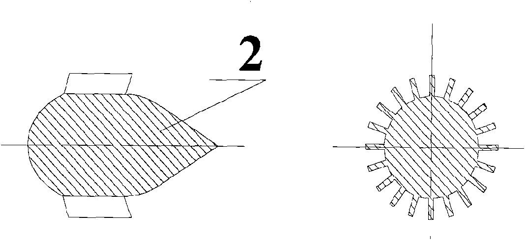
[0016] see figure 1 , 2, the present invention comprises the pipeline 1 that is made up of the inlet section 1-1 that is provided with gas inlet 4, scaling section 1-2, equal straight section 1-3 and expansion section 1-4, in the inlet section 1-1 of pipeline 1 1 is provided with a diversion spindle body 2 with cascades, an annular channel is formed between the diversion spindle body 2 with cascades and the pipeline 1, and a swirl recovery booster 3 is provided at the expansion section 1-4 of the pipeline 1, The swirl recovery booster 3 includes a housing 3-1 and a central cone 3-2 arranged in the housing 3-1, an annular gas outlet 7 is formed between the central cone 3-2 and the housing 3-1, and the housing 3 A liquid collection chamber 5 is formed between -1 and the expansion section 1-4 of the pipeline 1, and a liquid discharge port 6 is also opened at th...


PUM


Abstract

The invention provides a supersonic condensation and cyclone separation device, which leads air flow to generate powerful rotation in a blade-guiding manner at an entrance; then, a laval nozzle is used for coordinating with the separation device to lead the air flow to reach a supersonic speed and reduce temperature thereof greatly, thus condensing components with higher dew points and achieving the separation between the gas phase and the liquid phase under the action of the centrifugal force generated by the rotation of the air flow; and a highly-efficient liquid trap and a cyclone-recovering booster are arranged at the tail part of the nozzle. Compared with the existing supersonic separating device, the supersonic separation device of the invention has higher efficiency of separation and cyclone recovery under the same working conditions of low flow rate, for the device has the advantages that the flow channel of the device in a high-speed flow field area is smooth, the fractional resistance of the wall surface is low and the device is provided with the cyclone recovering booster suitable for the conditions of low flow rate. Since quite a lot of inland gas fields has low single-well flow rate in China, the device of the invention has wide application prospect in the field of natural gas treatment for the inland gas fields in China.

Description

technical field [0001] The invention relates to a liquefaction and separation technology of multi-component mixed gas, in particular to a supersonic condensation and cyclone separation device. Background technique [0002] Natural gas is clean and pollution-free, has high calorific value and is easy to use. However, the extracted natural gas is often mixed with liquid water, solid particles, water vapor and heavy hydrocarbons. In order to meet the requirements of natural gas transportation and use, the content of these impurities must be reduced, and the separation of water vapor and heavy hydrocarbons is the most difficult. At present, the separation technologies of water vapor and heavy hydrocarbons include solvent absorption, solid adsorption, membrane separation, low-temperature separation, supersonic separation, etc. Among them, the supersonic separation technology has simple structure, no need for external power, no need for personnel duties, and low processing and ope...

Claims


Application Information

Patent Timeline
IPC IPC(8): F25J3/06B04C3/00B04C3/04
Inventor 白博峰常春
Owner XI AN JIAOTONG UNIV
Why Eureka
Eureka Blog
Learn More