
Detection method of microfluidic chip based on photoacoustic technique and device thereof

A microfluidic chip and detection method technology, applied in the direction of measuring devices, separation methods, chemical instruments and methods, etc., can solve the problems of high actual price of fluorescent agents, complex optical equipment, and large volume, and achieve low cost and simple equipment , the effect of high sensitivity

Inactive Publication Date: 2009-12-30
JIANGXI SCI & TECH NORMAL UNIV
View PDF2 Cites 11 Cited by
  • Summary
  • Abstract
  • Description
  • Claims
  • Application Information

AI Technical Summary

Problems solved by technology

CN1410760A and CN2575662Y disclose the microfluidic chip detection system and its device based on the fluorescence detection method, the disadvantage of the fluorescence detection method is that the optical equipment used is complex, bulky, expensive, and the actual price of the fluorescent agent is high

Method used


Image

  • Detection method of microfluidic chip based on photoacoustic technique and device thereof

Examples


Embodiment 1

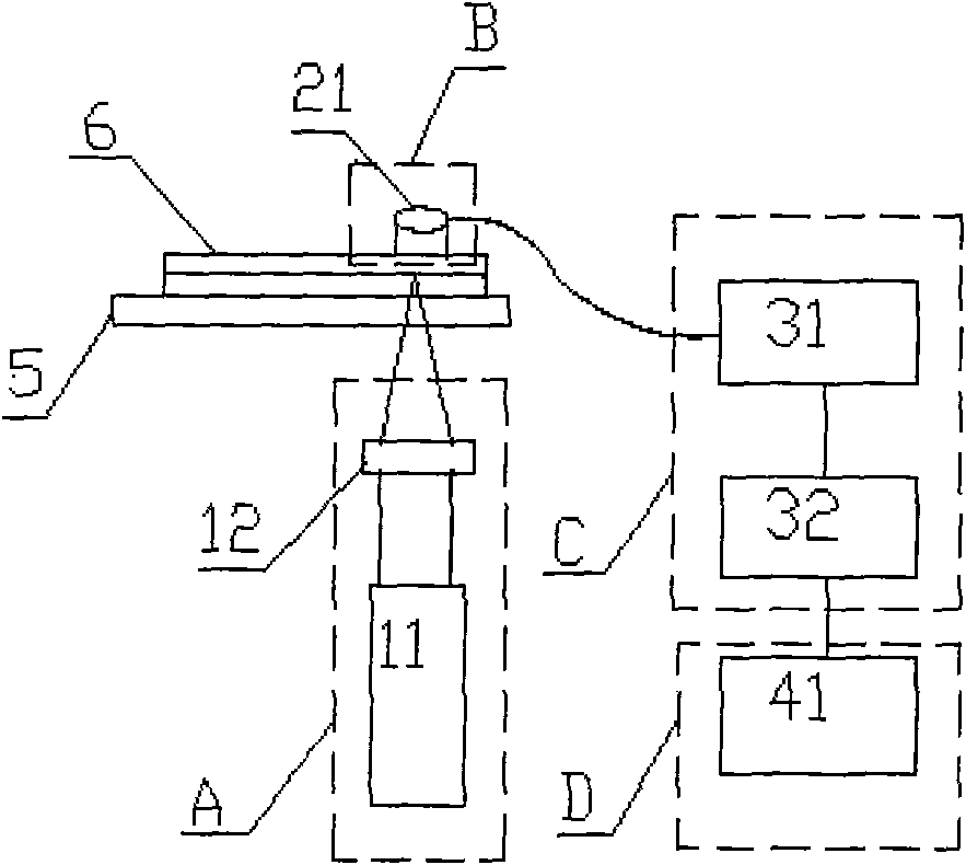
[0023] Example 1 as figure 1 Shown: a detection method using a microfluidic chip detection device, including the use of laser beams to irradiate the microfluidic chip added to the sample to be tested, to excite and generate photoacoustic signals, and the photoacoustic signals are collected and converted into electrical signals and then transmitted Data conversion unit and computer processing unit, the detection steps are as follows:

[0024] [1] Add the pretreated sample to be tested into the microfluidic chip for electrophoresis. Under the action of the electric field, the sample components with different mobility will be separated according to different mobility;

[0025] [2] Place the microfluidic chip 6 on the bidirectional translation platform 5, which can move in the X and Y directions, which makes it easier to install the chip and is also conducive to aligning and adjusting the position of the electrophoretic electrodes;

[0026] [3] The light source adopts a pulsed la...

Embodiment 2

[0029] Example 2 as figure 1 As shown: a microfluidic chip detection device based on photoacoustic technology includes an incident light generation unit A, a signal processing and data conversion unit C and a computer processing unit D, and also includes a photoacoustic signal detection unit B, and can be in X, A platform 5 with two-way translation in the Y direction;

[0030] The incident light generation unit A includes a laser 11 with a wavelength of 600--630nm or 640-800nm ​​and a focusing lens 12 between the platform 5 and the laser 11 located below the platform (5) that is bidirectionally translated. The focal point of the lens 12 is located on the separation channel of the microfluidic chip 6;

[0031] The photoacoustic signal detection unit B includes an ultrasonic sensor 21 located above the chip;

[0032] The signal processing and data conversion unit C is composed of a signal amplifier (31) including a preamplifier and a main amplifier and a single-chip microcompu...


PUM

PropertyMeasurementUnit
Wavelengthaaaaaaaaaa

Abstract

The invention relates to a detection method of a microfluidic chip based on a photoacoustic technique and a device thereof. The detection method comprises the following steps of: adopting the microfluidic chip consisting of an incident light generating unit A, a photoacoustic signal detection unit B, a signal processing and data conversion unit C, a computer processing unit D and a platform capable of translating in double directions of X direction and Y direction; adding pretreated samples to be detected into the microfluidic chip for electrophoresis, emitting signals by the computer processing unit according to commands, and controlling electrophoresis and high voltage after being converted by a single chip microprocessor D / A; under the effect of electric field, separating samples with different mobility according to different mobility, absorbing light power by the samples to generate photoacoustic signals by a spot detection window, collecting photoacoustic signals by an ultrasonic sensor, converting the photoacoustic signals into electric signals, converting the photoacoustic signals received by the sensor into digital signals by an analog-to-digital converter and being capable of determining the types and properties of the samples to be detected after being processed by signals of the computer. The detection method has the advantages of high sensitivity, low cost and convenient operation.

Description

technical field [0001] The invention relates to a detection method and a detection device thereof, in particular to a photoacoustic technology-based microfluidic chip detection method and a device thereof. Background technique [0002] Micro Total Analysis System (μ-TAS), also known as Lab-on-a-chip, is a technology that integrates sample preparation, biology and chemical reactions involved in the fields of chemistry and biology. Processes such as separation and detection are miniaturized or basically miniaturized onto a chip of a few square centimeters to complete different biological or chemical reaction processes and analyze their products. It is a micro and comprehensive system. [0003] At present, the micro-full analysis system can be divided into two categories: chip type and non-chip type, among which the chip type is the focus of the development of this technology. According to the chip structure and working mechanism of the chip, it can be divided into microarray ...

Claims


Application Information

Patent Timeline
IPC IPC(8): G01N21/17G01D5/62B01D57/02
Inventor 刘国栋曾文平曾吕明徐景坤
Owner JIANGXI SCI & TECH NORMAL UNIV
Learn More