
Cutting insert for high-efficient cutting

一种插入件、高效的技术,应用在用于车床的刀具、刀夹的附件、切削刀片等方向,能够解决切割插入件强度降低、切割刃数目有限、切割插入件损坏等问题,达到使用寿命和经济效率增加、提高材料去除速率、高生产率的效果

Active Publication Date: 2009-12-02
KORLOY
View PDF0 Cites 6 Cited by
  • Summary
  • Abstract
  • Description
  • Claims
  • Application Information

AI Technical Summary

Problems solved by technology

[0007] However, when it comes to ordinary single-sided cutting inserts (which are usually used for milling), the number of cutting edges that can be used is limited due to the single-sided structure
Also, because the clearance angle is determined in its side surface, the common single-sided cutting insert has the disadvantage that the strength of the cutting insert is reduced, so that the cutting insert may be damaged due to high speed and fast feed cutting

Method used


Image

  • Cutting insert for high-efficient cutting
  • Cutting insert for high-efficient cutting
  • Cutting insert for high-efficient cutting

Examples


Embodiment Construction

[0036] The above and other objects, features and advantages of the present invention will be more clearly understood through the following detailed description.

[0037] Preferred embodiments of the present invention will be described below with reference to the accompanying drawings.

[0038] Reference is now made to the drawings, wherein like reference numerals represent the same or similar parts throughout the different drawings. Also, in the description of the present invention, in order to more clearly introduce the gist of the present invention, detailed descriptions of well-known techniques and structures will be omitted.

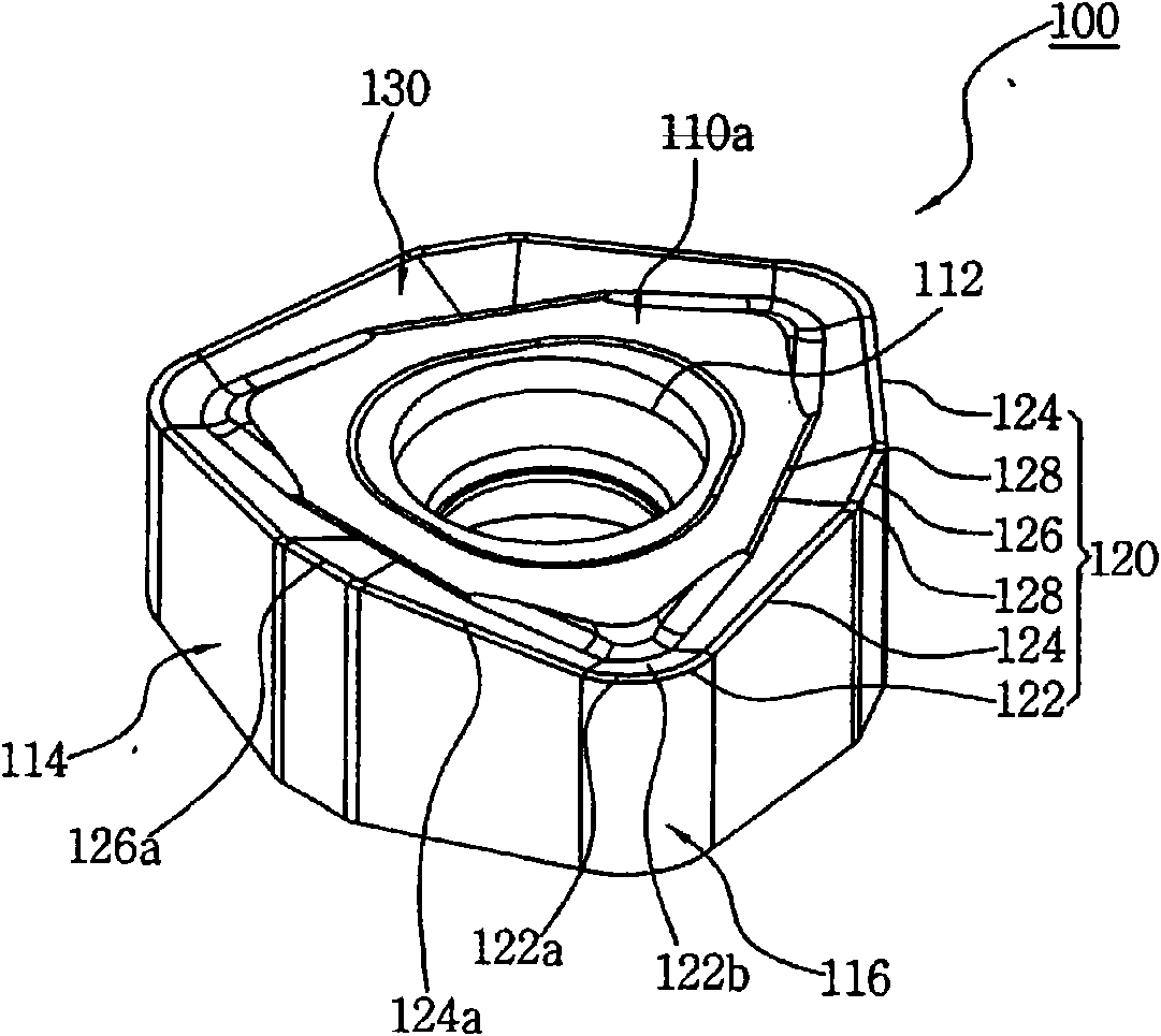
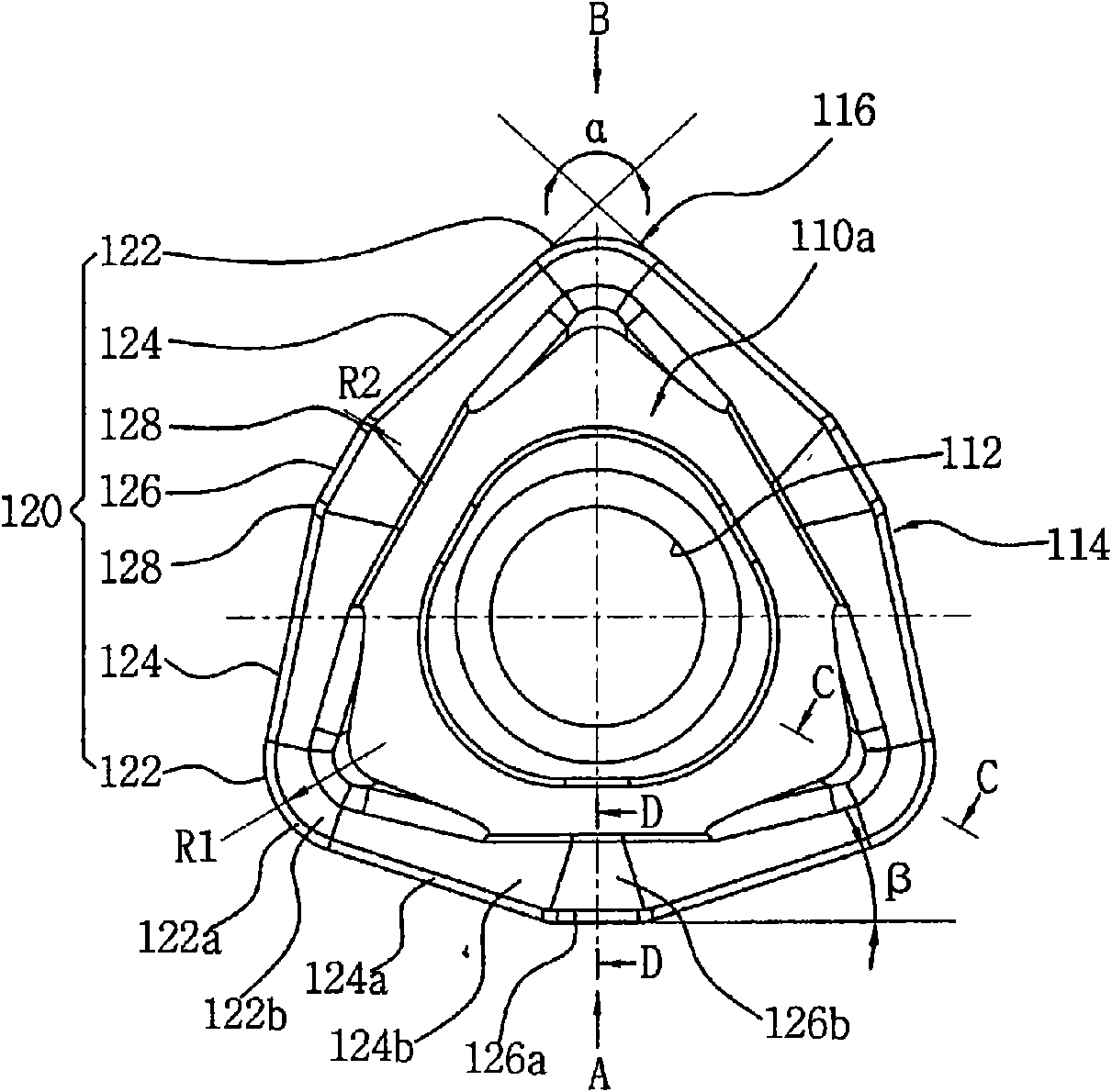
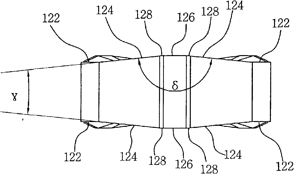
[0039] figure 1 is a perspective view of a cutting insert for efficient cutting according to the present invention. figure 2 yes figure 1 Plan view of the cutting insert. image 3 is to indicate that the cutting insert is made from figure 2 The view when looking in the direction indicated by the letter "A". Figure 4 is to indicate that the cut...


PUM


Abstract

A cutting insert for high-efficiency cutting is disclosed. The cutting insert includes an upper surface (110a), a lower surface (HOb), side surfaces (114) and corner side surfaces (116), which connect the side surfaces to each other. A circular opening is formed through the central portions of the upper and lower surfaces. In the cutting insert, cutting edges are formed by respective junctions between one of the upper and lower surfaces and the side surfaces and between one of the upper and lower surfaces and the corner side surfaces. The cutting edges comprise three corner cutting edges (122), six major cutting edges (124), which extend from opposite ends of the corner cutting edges towards the neighbor corner cutting edges, and three minor cutting edges (126), which are connected between the major cutting edges. Furthermore, the cutting edges may be formed on both the upper surface and the lower surface.

Description

technical field [0001] The present invention relates to a cutting insert for high-efficiency cutting, and more particularly, to a cutting insert for high-efficiency cutting, which has increased hardness so that the cutting process can be stably performed even with fast-feed cutting, Among them, the number of cutting edges is increased, thus prolonging the service life of the cutting insert, and the cutting insert can be used for milling operation and turning operation, thus realizing a multi-functional structure and being economical, and it can also improve cutting efficiency. productivity and achieve high-quality cutting. Background technique [0002] Generally, cutting tools are used to cut ferrous, non-ferrous and non-metallic workpieces. Typically, cutting tools are held by the machine and cut the workpieces so that they are formed into the desired shape. Such cutting tools comprise a cutting insert having a cutting edge and a cutter body supporting the cutting insert....

Claims


Application Information

Patent Timeline
Patent Type & Authority Applications(China)
IPC IPC(8): B23C5/02
CPCB23B2200/087B23B2200/0495B23C5/06B23B27/141B23B2200/286B23C5/202Y10T407/23B23C5/02B23C5/20
Inventor 成旭重成仁植
Owner KORLOY
Learn More