Method, device and system for realizing power over Ethernet (POE)
An implementation method, Ethernet technology, applied in the implementation field of Power over Ethernet POE, can solve the problems of reducing the stability of the system operation, failing to realize redundant backup and load balancing, affecting the normal operation of powered equipment, etc., to improve stability Effect
- Summary
- Abstract
- Description
- Claims
- Application Information
AI Technical Summary
Problems solved by technology
Method used
Image
Examples
Embodiment 1
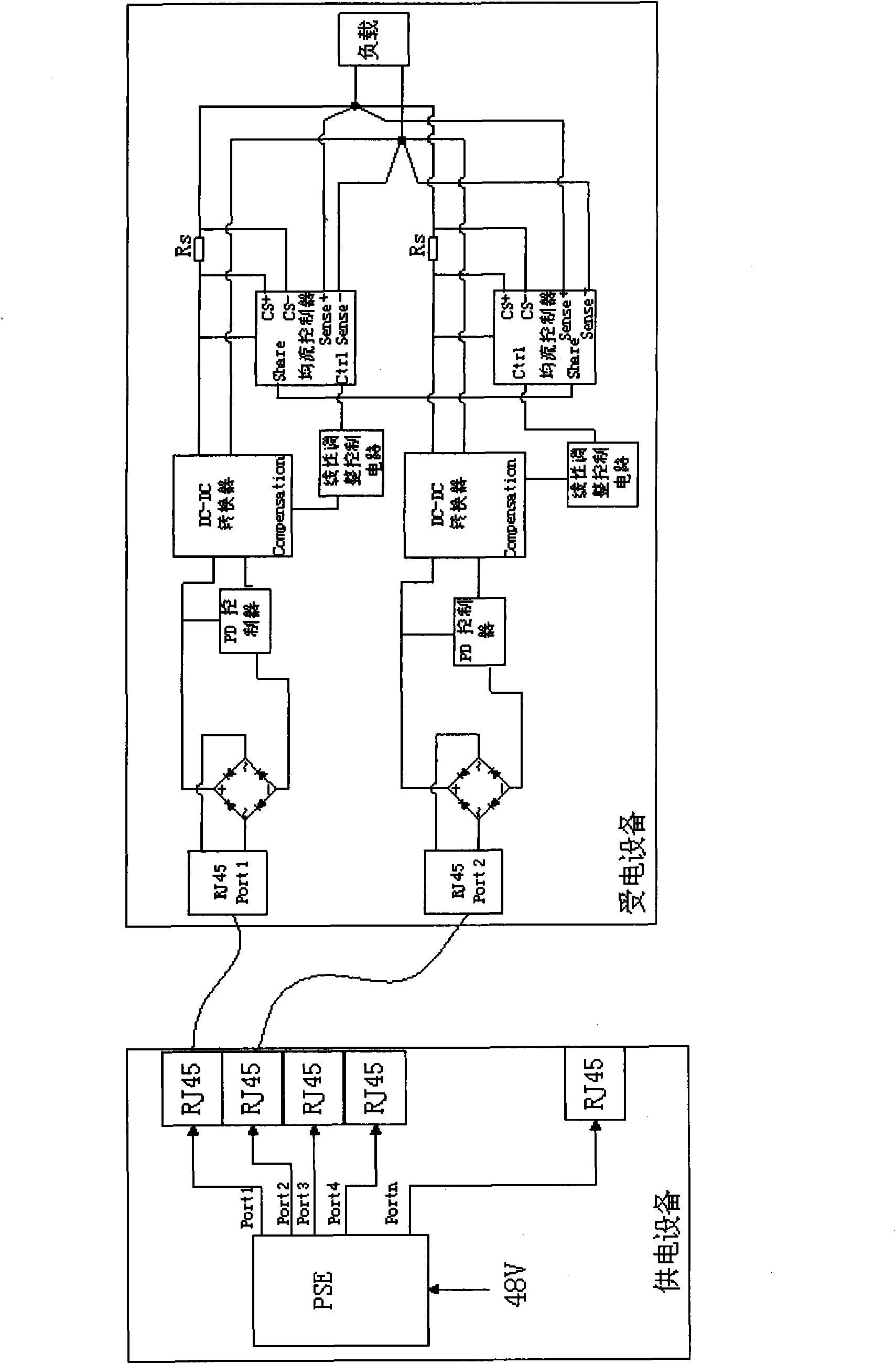
[0037] In the first application embodiment, the dual-port power supply is taken as an example to describe the POE implementation solution provided by the embodiment of the present invention in detail. image 3 The schematic diagram of the circuit structure for implementing Embodiment 1 of the present invention is shown, wherein, the PSE side uses two RJ45 interfaces to supply power, and the powered equipment side uses two RJ45 interfaces to receive the DC power from the PSE side. When the data line pair is used for power supply, on the PD side, the circuit corresponding to each interface needs to be equipped with a transformer that supports POE ( image 3 not shown in ); when the idle line pair is used for power supply, there is no need to set a transformer on the PD side. Therefore, in the specific circuit structure, in order to support two power supply modes, each interface is connected to its corresponding PD control through a diode bridge. and a DC-DC converter, each DC-DC...
Embodiment 2
[0046] In the second application embodiment, the dual-port power supply is taken as an example to describe the POE implementation solution provided by the embodiment of the present invention in detail. Figure 5 The schematic diagram of the circuit structure for realizing the second embodiment of the present invention is shown, wherein, the PSE side uses two RJ45 interfaces to supply power, and the powered equipment side uses two RJ45 interfaces to receive the DC power on the PSE side, and are respectively connected to their respective corresponding terminals through diode bridges. PD controller and load balancing controller, PD controller is connected to DC-DC converter through MOSFET or Darlington tube or power transistor. Wherein, the control output terminal of the load balance controller controls the MOSFET or Darlington tube or the power triode to work in the linear range through the linear adjustment circuit, which is used to compensate the current difference caused by th...
Embodiment 3
[0055] There are many ways to realize the load balancing controller. The application embodiment of the present invention takes the load sharing controller chip, such as UC3907, as an example, and introduces in detail the way to realize load balancing through the load sharing controller chip:
[0056] The load sharing controller chip is composed of high input impedance voltage amplifier, ground amplifier, differential current amplifier and adjustment amplifier. Wherein, the impedance voltage amplifier is a buffer with constant gain, and provides a +0.25V offset to complete the detection of the negative Sense (voltage detection negative terminal), and the output result of the ground amplifier is added with an approximately 1.75V The offset forms the bandgap reference voltage.
[0057] The circuit connection relationship and working process of the load sharing controller chip are as follows:
[0058] The negative input terminal of the adjustment amplifier is connected to the dif...
PUM
 Abstract
Description
Claims
Application Information
 - R&D
- Intellectual Property
- Life Sciences
- Materials
- Tech Scout
- Unparalleled Data Quality
- Higher Quality Content
- 60% Fewer Hallucinations
Browse by: Latest US Patents, China's latest patents, Technical Efficacy Thesaurus, Application Domain, Technology Topic, Popular Technical Reports.
© 2025 PatSnap. All rights reserved.Legal|Privacy policy|Modern Slavery Act Transparency Statement|Sitemap|About US| Contact US: help@patsnap.com


