
Single-ended fluorescent lamp slice pipe bending and molding device

A fluorescent lamp sheet and molding device technology, which is applied in glass molding, glass remolding, and glass manufacturing equipment, etc., can solve the problems of increased scrap rate, low production efficiency, and reduced molding speed, so as to save waste and improve production. The effect of improving the efficiency and the pass rate of the mold

Inactive Publication Date: 2009-12-02
YIXING CHENHONG LIGHTING APPLIANCE
View PDF5 Cites 4 Cited by
  • Summary
  • Abstract
  • Description
  • Claims
  • Application Information

AI Technical Summary

Problems solved by technology

There are deficiencies in this pipe bending method and device: for example, the two processes of pipe bending need to be handed over by two pairs of manipulators, that is, the first pair of manipulators will combine the heated and softened glass straight pipes with the bent pipe, and then the second pair of manipulators will take over. Send it to the position of the final shaping mold, and the mold will be closed and shaped (U-shaped tube) or bent to shape (such as lotus lamp tube). This increased length needs to be cut off, which increases the waste of the process section required by the process due to the ineffective lamp tube. At the same time, some special sheet tubes that require relatively short unmelted soft sections are not suitable for mechanical bending because there is no upper and lower handover position. Rely on manual pipe bending; secondly, due to the need for two sets of manipulators to hand over the process, the molding speed will be reduced accordingly, and the production efficiency will not be improved; thirdly, the handover procedure will cause the molten glass tube to change shape due to the prolonged handover time. And the jitter during handover will lead to a decrease in the pass rate of the bent sheet tube into the mold and an increase in the scrap rate
The handover of the two pairs of manipulators brings about three major disadvantages: low molding speed, low pass rate of mold entry, increased process and waste of ineffective glass tubes. People are also aware of these three shortcomings, but they have not been effectively solved for a long time, and have long plagued single-ended fluorescent lamp tubes. Tube Forming

Method used


Image

  • Single-ended fluorescent lamp slice pipe bending and molding device
  • Single-ended fluorescent lamp slice pipe bending and molding device
  • Single-ended fluorescent lamp slice pipe bending and molding device

Examples


Embodiment 1

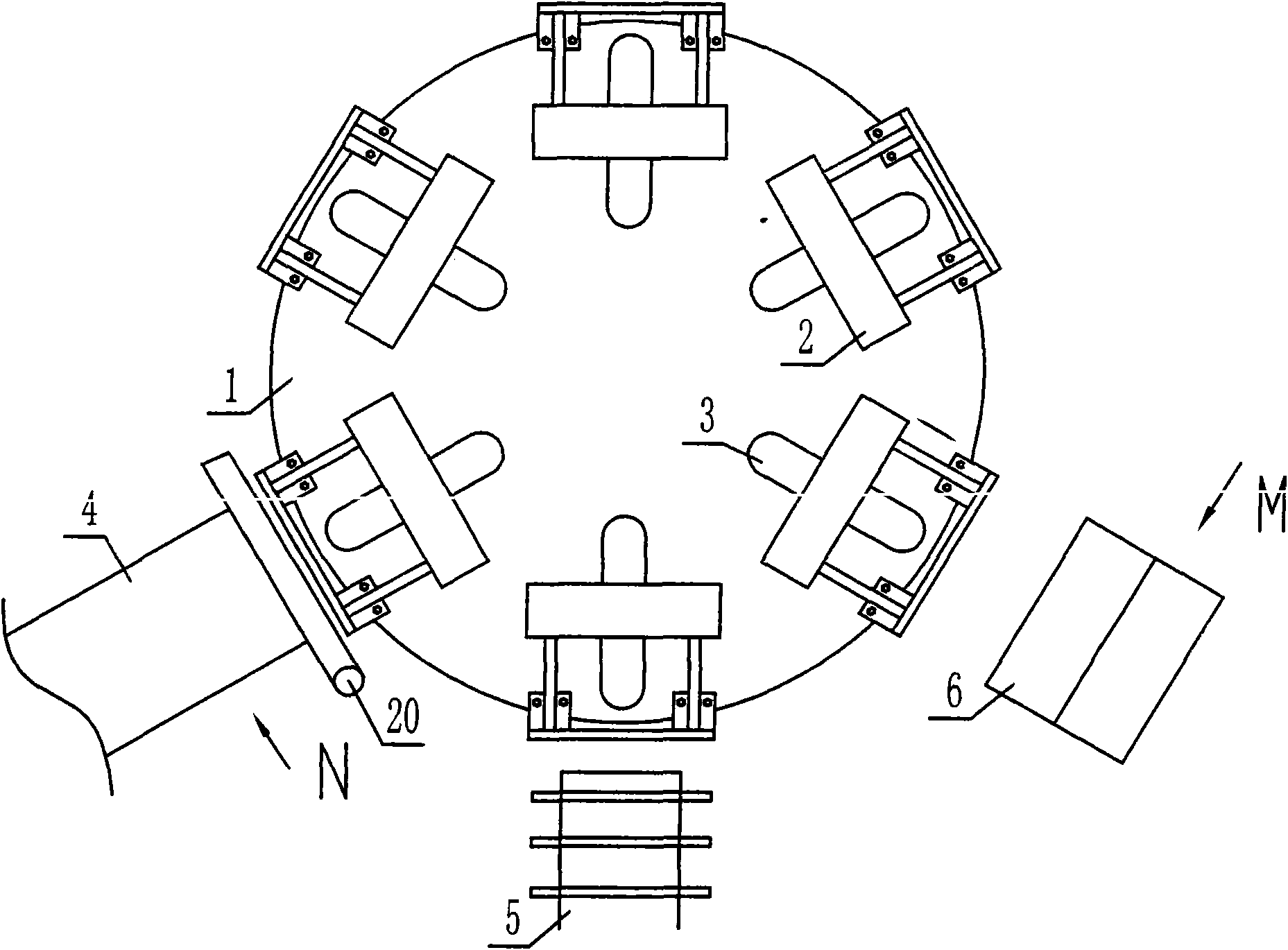
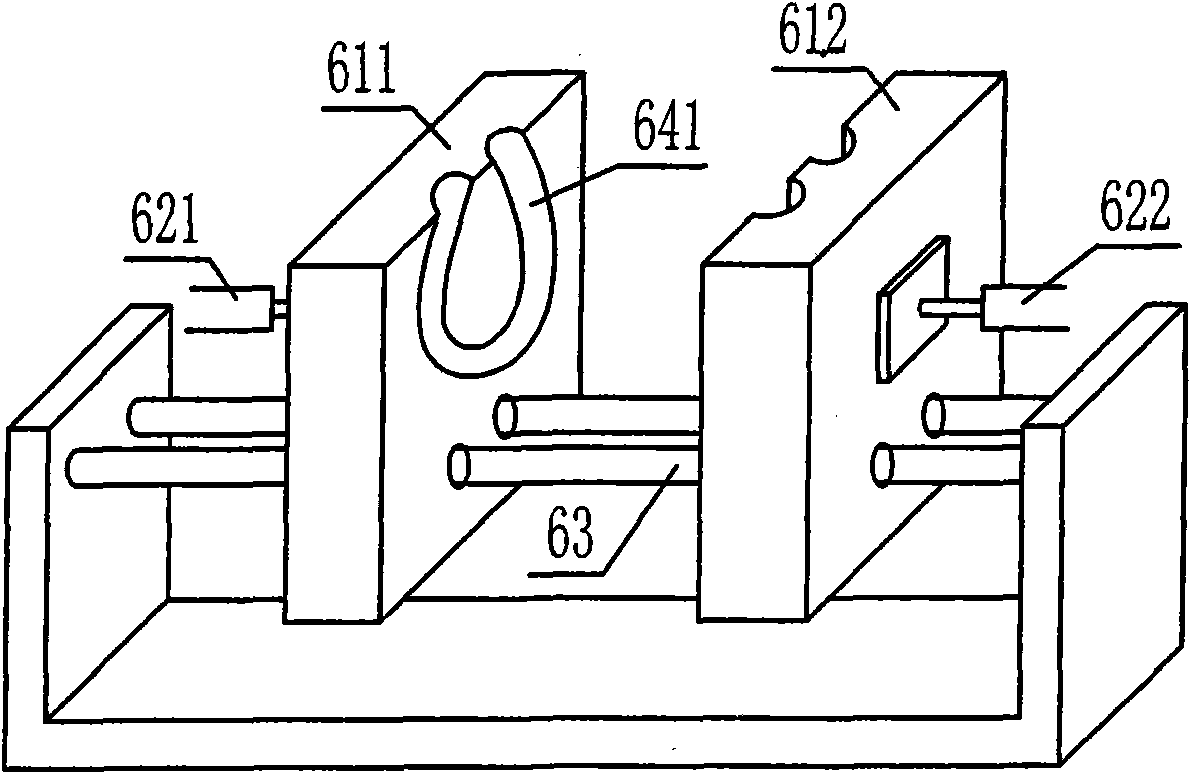
[0033] Embodiment 1: Referring to the accompanying drawings (except 15, 16, and 17), the single-ended fluorescent lamp tube bending device of the present invention includes a gap rotating turntable 1, and several sets of manipulator assemblies 2 are evenly distributed on the circumference of the turntable (6 sets in the figure, Depending on the size of the turntable area), each manipulator position of the turntable has radial guide grooves 3 for the manipulators to move radially forward and backward. There are glass tube heating and softening devices 5 arranged adjacently outside the turntable, and the molds can be separated / matched 6 for shaping, and The unloading tube receiving device 4 after the forming of the back. Shaping mold 6 ( figure 2 ), the same as the prior art, is composed of two templates 611, 612 that move toward each other according to the guide rail 63 and can be combined / separated. The matching surface is processed with a lamp tube shaping groove 641. The m...

Embodiment 2

[0035] Example 2: see Figure 15 , as embodiment 1, drive two manipulators to rotate oppositely to close up the elbow, separate to take over, can be fixed on the side-by-side gear 22,23 of two manipulators one end by a lifting rack 21 meshing up and down. It becomes a rack for lifting up and down, and at the same time drives the two gears that mesh with each other to rotate in opposite directions, so that the pipe bending manipulator fixed on the gears rotates in opposite directions to close the pipe bend / release the connecting pipe. In addition, it can also realize the closing / undrawing of the manipulator through, for example, a cam driving a connecting rod.

Embodiment 3

[0036] Embodiment 3: see Figure 16 , as mentioned above, the mold cavity 31 of the shaping die 6 can be a vertically curved structure according to the requirements of bending the sheet tube. Drive mold to separate / close power, also can be the rotating cam 19 that turntable rotates power output, the crank arm connecting rod 30 that makes sliding contact with it moves apart / closes.

[0037] In addition, the sizing mold 6 can also be set at the same station of the glass tube heating and softening device. Separately drop back into position.


PUM


Abstract

The invention relates to improvement of a single-ended fluorescent lamp slice pipe bending and molding device, which is characterized in that: a plurality of mechanical arm folding / separating pipe bending devices are alternately arranged on the periphery of a turntable in clearance rotation, and at least can perform radial expansion; and a glass tube heating and softening device and a separating / folding mould are arranged on the radial outside of the turntable. Compared with the prior art, a pair of mechanical arms is needed only, and can complete the whole process of pipe bending to pipe unloading, and continuous pipe bending operation after connecting pipes on the heating and softening device, so the single-ended fluorescent lamp slice pipe bending and molding device not only saves a pair of mechanical arms, but also obviously improves production efficiency by over 15 percent; no connection action exists, so bent pipes cannot be deformed, and the mould-in qualification rate can be improved by over 15 percent; and a pair of mechanical arms completes the whole process of bending pipes, so the single-ended fluorescent lamp slice pipe bending and molding device saves the waste of process connecting pipe sections in the prior pipe bending process, can save about 20mm of glass tube on two end heads for bending the slice pipe with the same specification, and can be suitable for bending and molding slice pipes of which the straight pipe sections are short.

Description

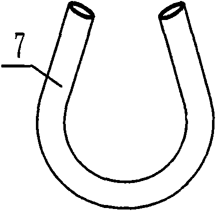
technical field [0001] The invention relates to the improvement of a single-end fluorescent lamp tube bending device, in particular to a bending device with high bending efficiency and finished product, saving glass tubes. Background technique [0002] Single-ended fluorescent lamp tubes, whether they are U-shaped, flower-shaped or lotus-shaped lamp tubes, are made of straight glass tubes that go through a bending process and two processes of moving into the mold and setting them. It can be rounded and shaped, or pressurized into the mold and then injected with pressure gas to make it smooth and shaped. For example, the simple U-shaped sheet tube, the straight tube is heated and softened, and the two ends of the glass tube are clamped by the manipulator to form a U-shape, and then moved into the mold that can be combined / separated to shape; the lotus lamp tube is held by the manipulator. The two ends of the glass tube are combined and bent into a U-shape or roughly a U-shap...

Claims


Application Information

Patent Timeline
IPC IPC(8): C03B23/045C03B23/06
CPCY02P40/57
Inventor 吴建新凌峰杨洪刚
Owner YIXING CHENHONG LIGHTING APPLIANCE
Learn More