
Wide load characteristic ZVZCS three-level DC-DC converter

A DC-DC, three-level technology, applied in the direction of adjusting electrical variables, high-efficiency power electronic conversion, output power conversion devices, etc., can solve problems such as excessive voltage spikes, large switching losses, and damage to switching tubes. Low loss, fast return to zero, and the effect of expanding the scope of application

Inactive Publication Date: 2009-11-25
HARBIN INST OF TECH
View PDF0 Cites 14 Cited by
  • Summary
  • Abstract
  • Description
  • Claims
  • Application Information

AI Technical Summary

Problems solved by technology

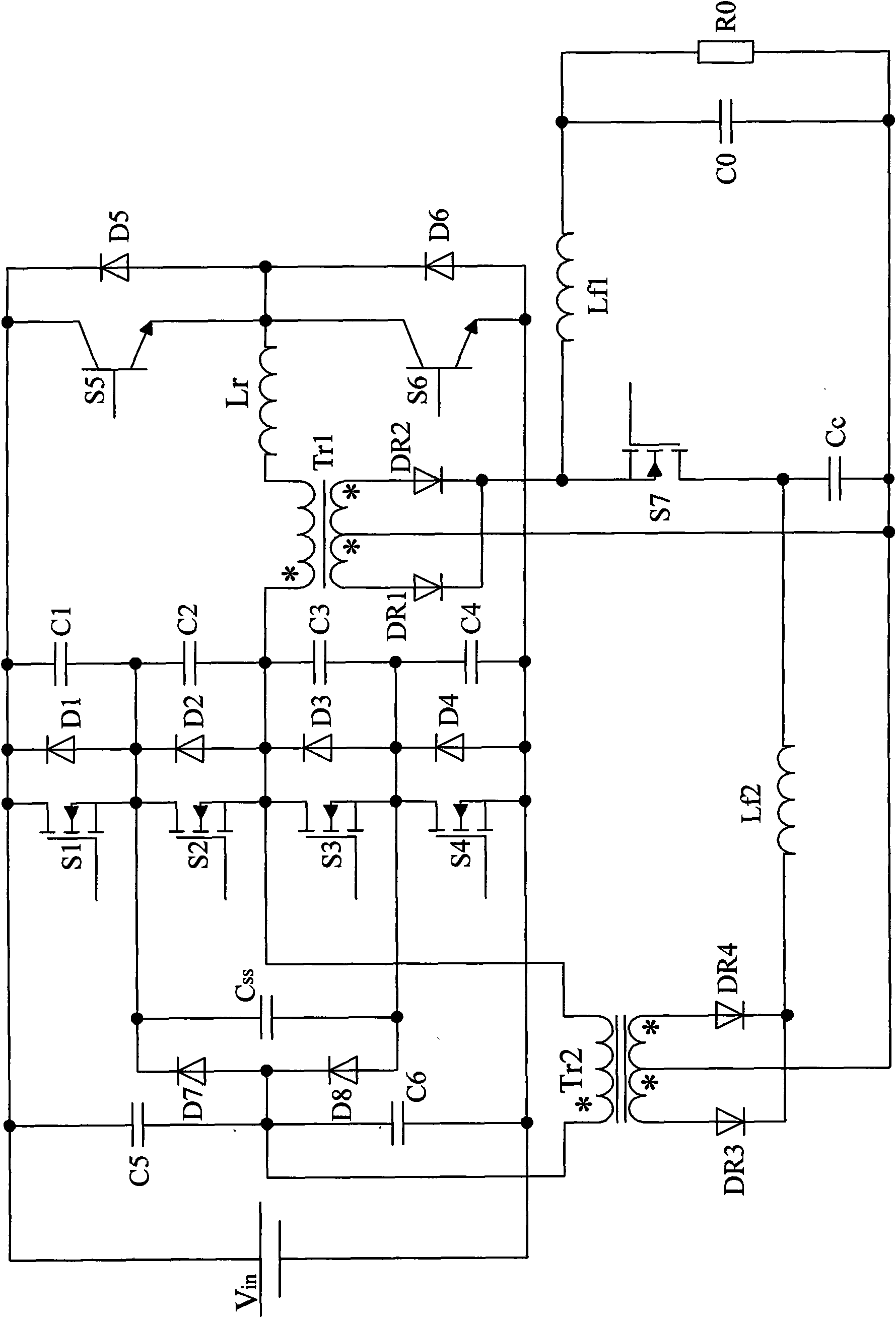
[0003] In order to solve the problems of large switching losses and excessive voltage peaks in the existing three-level converters, which may easily cause damage to the switch tube and serious electromagnetic interference, the present invention proposes a ZVZCS three-level with wide load characteristics DC-DC Converter

Method used


Image

  • Wide load characteristic ZVZCS three-level DC-DC converter
  • Wide load characteristic ZVZCS three-level DC-DC converter
  • Wide load characteristic ZVZCS three-level DC-DC converter

Examples


specific Embodiment approach 1

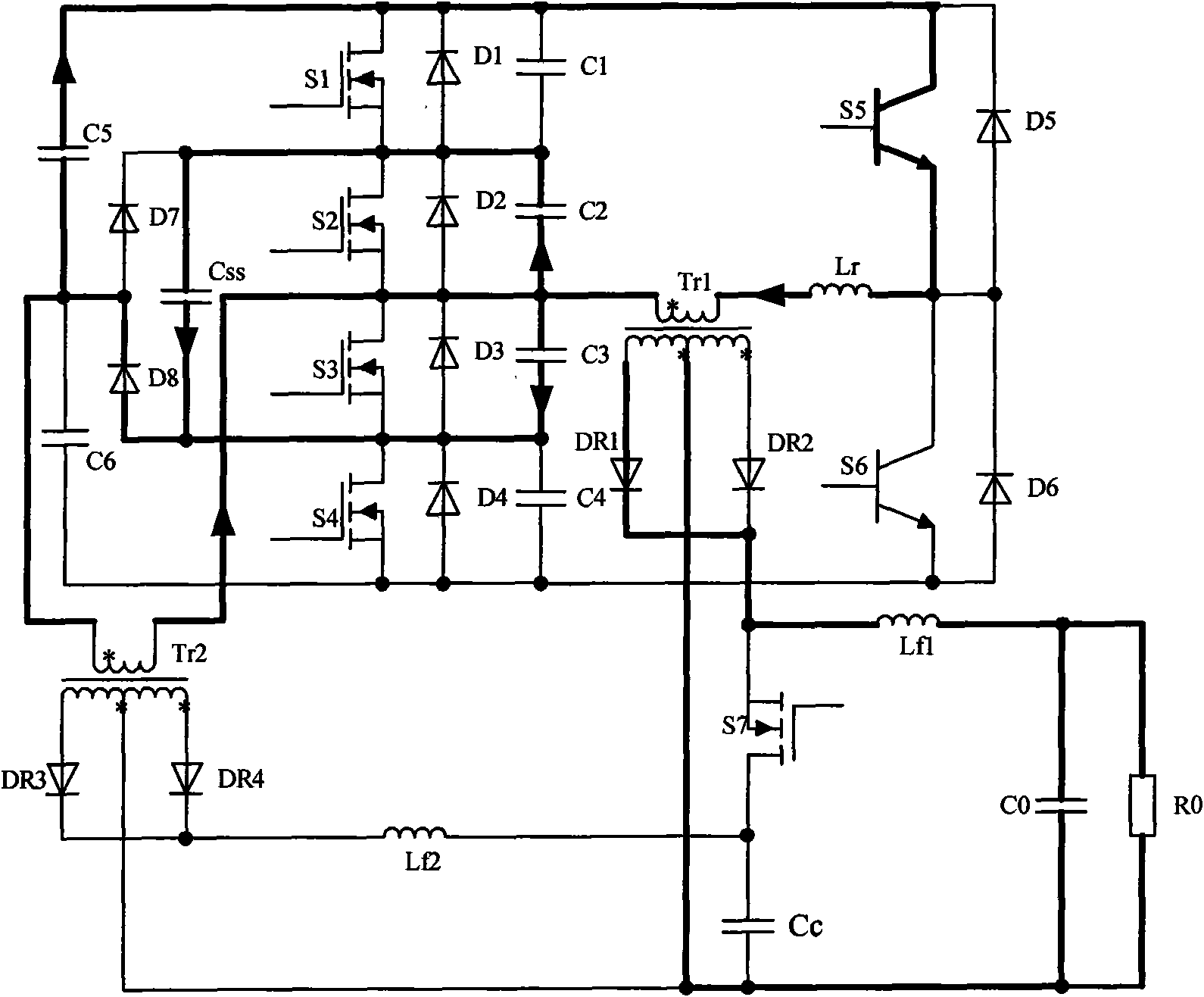
[0007] Specific implementation mode one: combine figure 1Describe this embodiment, this embodiment includes the first diode D1 to the eighth diode D8, the first capacitor C1 to the sixth capacitor C6, the first insulated gate field effect transistor S1 to the fourth insulated gate field effect transistor Tube S4, fifth transistor S5, sixth transistor S6, flying capacitor Css, resonant inductor Lr, first inductor Lf1, filter capacitor C0, load resistor R0, first rectifier diode DR1, second rectifier diode DR2 and the main transformer Tr1; one end of the fifth capacitor C5 is simultaneously connected to the positive voltage end, the drain end of the first insulated gate field effect transistor S1, the cathode of the first diode D1, one end of the first capacitor C1, and the fifth triode The collector end of the tube S5 is connected to the cathode of the fifth diode D5; the other end of the fifth capacitor C5 is simultaneously connected to the anode of the seventh diode D7, the c...

specific Embodiment approach 2

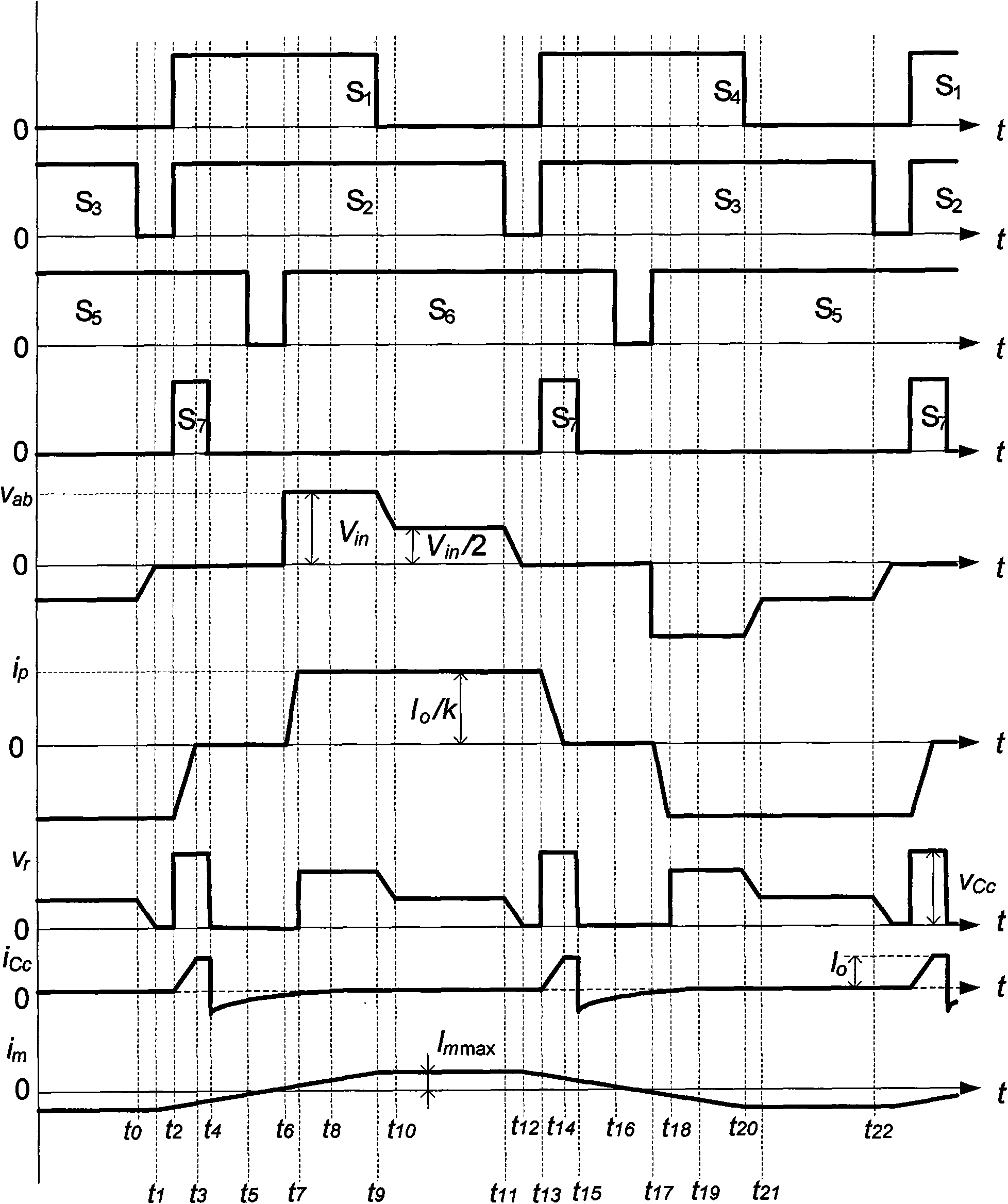
[0047] Specific embodiment 2: This embodiment is described in conjunction with the figure. The difference between this embodiment and specific embodiment 1 is that the main power parameters of the converter described in the present invention are: U in = 240V ~ 320V, U o =24V, the rated output current is 6A, and the switching frequency is 50kHz. The first insulated gate field effect transistor S1 to the fourth insulated gate field effect transistor S4 and the seventh insulated gate field effect transistor S7 adopt the model IRF740, and the first capacitor C1 to the fourth capacitor C4 are the junction capacitances of the switch tubes, The fifth triode S5 to the sixth triode S6 adopt the model HGTP20N60C3, the clamp capacitor Cc=2.2μF, and the main transformer Tr1 has a transformation ratio of k 1 =63:9, auxiliary transformer Tr2 ratio k 2 =36:12, the model of the first rectifier diode DR1 to the fourth rectifier diode DR4 is MUR1520, the first inductor Lf1=50 μH, and the filt...


PUM


Abstract

A wide load characteristic ZVZCS three-level DC-DC converter relates to a three-level converter. The aim of the invention is to settle the problems of large switching loss, generation of large voltage peak, easily switching tube damage and series electromagnetic interference problem existing in the prior three-level converter. The anode of a voltage source is simultaneously connected with one end of a first capacitor, one end of a fifth capacitor, a drain end of a first insulated-gate type field effect transistor, the cathode of a first diode, the cathode of a fifth diode and the collector electrode end of a fifth triode. The cathode of the voltage source is simultaneously connected with one end of a fourth capacitor, one end of the sixth capacitor, a source end of a fourth insulated-gate type field effect transistor, an anode of a fourth diode, an anode of a sixth diode and the emitter end of a sixth triode (S6). The wide load characteristic ZVZCS three-level DC-DC converter of the invention is also added with an auxiliary rectifying circuit and an active clamp circuit. The wide load characteristic ZVZCS three-level DC-DC converter of the invention has the advantages of high resetting speed of the primary side current, no overshoot voltage of the secondary side, etc. Furthermore the wide load characteristic ZVZCS three-level DC-DC converter of the invention settles the problems of duty ratio loss, primary side circumfluence, parasitic oscillation, etc. The efficiency of the converter is increased. The switching loss and the electromagnetic interference are reduced.

Description

technical field [0001] The invention relates to a three-level DC-DC converter, in particular to a ZVZCS three-level converter. Background technique [0002] In some occasions, such as arc welding power supply, etc., it will often run in an open circuit state and cannot be shut down. In this case, the ZVS (Zero-Voltage Switching) condition of the ordinary three-level converter disappears, and the switching tube works in a hard switching state, with large switching losses and low efficiency, and will generate large voltage spikes, which may easily cause the switching tube At the same time, the electromagnetic interference (Electro Magnetic Interference, referred to as EMI) is a serious problem, which affects the normal operation of the surrounding electronic equipment. Contents of the invention [0003] In order to solve the problems of large switching losses and excessive voltage peaks in the existing three-level converters, which may easily cause damage to the switch tube...

Claims


Application Information

Patent Timeline
Patent Type & Authority Applications(China)
IPC IPC(8): H02M3/155
CPCY02B70/1491Y02B70/10
Inventor 孙铁成曲慧星高婷周永李瑞
Owner HARBIN INST OF TECH
Learn More