Light shield, hole arrangement and method for reducing dishing of metal plug

A metal plug, metal plug technology, applied in the field of hole layout for providing metal plugs

Inactive Publication Date: 2014-07-09
RICHTEK TECH
View PDF4 Cites 0 Cited by
  • Summary
  • Abstract
  • Description
  • Claims
  • Application Information

AI Technical Summary

Problems solved by technology

[0004]Therefore, the known hole layouts and methods of forming them suffer from the above-mentioned inconveniences and problems

Method used


Image

  • Light shield, hole arrangement and method for reducing dishing of metal plug
  • Light shield, hole arrangement and method for reducing dishing of metal plug
  • Light shield, hole arrangement and method for reducing dishing of metal plug

Examples


Embodiment Construction

[0067] The present invention will be further described below in conjunction with embodiment and accompanying drawing.

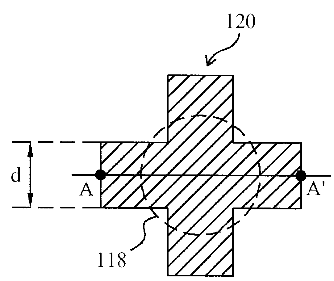
[0068] see now Figure 3A and Figure 3B , Figure 3A and Figure 3B yes figure 2 Schematic illustration of the dishing phenomenon caused by the hole layout shown. As shown in the figure, the dishing portion 134 of the tungsten plug 132 is close to the cross portion 118 in the hole 120 , which is the critical portion of the hole 120 .

[0069] see again Figure 4 , Figure 4 is a schematic diagram according to the first embodiment of the present invention. As shown, the reticle 210 includes a hole pattern 220 fabricated on a substrate, the hole pattern 220 having a shape defined by a closed boundary and a reduced critical portion 222 within the boundary, the critical portion The minimum dimension d2 of 222 is intentionally reduced to be smaller than the dimension d1 of the original layout design. The optical lithography process 230 is performed with...


PUM


Abstract

A hole layout for reducing dishing of metal plugs, comprising a substrate and an insulating layer, wherein the insulating layer is on the substrate, and a hole for filling metal is provided in the insulating layer, and the hole is Having a profile in the horizontal plane defined by a closed boundary and a reduced critical portion within said boundary for reducing dishing of said metal plug. The hole layout for reducing metal plug dishing of the present invention has the advantages of reducing the dishing phenomenon of metal plugs filled in the holes, reducing the risk of the manufacturing process, increasing the freedom of photomask layout and reducing the chip area.

Description

technical field [0001] The present invention relates to a layout of integrated circuits, in particular, a layout of holes providing metal plugs. Background technique [0002] In the semiconductor manufacturing process, the layout pattern on the photomask is mainly transferred to the wafer (wafer) through the optical lithography manufacturing process, and then the integrated circuit structure is formed through the manufacturing processes such as deposition and etching. Therefore, the layout pattern on the photomask Pattern design needs to consider the capabilities of various manufacturing processes, resulting in many layout rules. Because it is necessary to design the layout pattern of the circuit on the reticle according to the layout rules, and then transfer the layout pattern on the reticle to the wafer accurately, so that the pattern transferred to the wafer is exactly the same as the layout pattern on the reticle. Anastomosis has been the focus of research. For exampl...

Claims


Application Information

Patent Timeline
Patent Type & Authority Patents(China)
IPC IPC(8): G03F1/36
Inventor 杨清尧苏宏德刘景萌
Owner RICHTEK TECH
Why Eureka
Try Eureka